background image

4601 I-V Meter Operation Manual

3.2.3 Changing Measurement Function and Range

3-9

3.2.3

Changing Measurement Function and Range

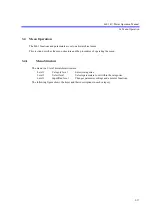
As the 4601 includes three AD converters (ADC1 to ADC3), it can measure three points simultaneously.
The three measurement points are shown below, and among which ADC3 has eight measurement 
functions.

The ADC3 function is selectable from the eight functions in the DC source mode; however it is fixed to
reference cell current measurement Ir in the sweep source mode.

This section describes how to set the above eight measurement functions and ranges.

(1) ADC1:

Output voltage measurement

Vm

(2) ADC2:

Output current measurement

Im

(3) ADC3:

Reference cell/external voltage/temperature measurement

Ir

: Reference cell current measurement

Em

: External voltage measurement

Tc1 : Ch1 T-type thermocouple measurement

Pt1

: Ch1 resistance bulb (Pt) temperature measurement

Ad1 : Ch1 IC sensor AD590 temperature measurement

Tc2 : Ch2 T-type thermocouple measurement

Pt2

: Ch2 resistance bulb (Pt) temperature measurement

Ad2 : Ch2 IC sensor AD590 temperature measurement

Содержание 4601 I-V Meter

Страница 1: ...MANUAL NUMBER C Printed in Japan ADC CORPORATION All rights reserved 4601 I V Meter Operation Manual FOE 00000066A00 First printing Sep 22 2011 2011 Cover...

Страница 2: ......

Страница 3: ...hazardous situation which will result in personal injury or a damage to property including the product Basic Precautions Please observe the following precautions to prevent fire burn electric shock a...

Страница 4: ...ing to a restriction on operation Safety Marks on the Product The following safety marks can be found on ADC products ATTENTION Refer to manual Protective ground earth terminal DANGER High voltage CAU...

Страница 5: ...f important data The data stored in the disk may become damaged if the product is mishandled The hard disc has a limited life span which depends on the operational conditions Note that there is no gua...

Страница 6: ...degree is defined by IEC61010 1 and described below Impulse withstand voltage over voltage category II defined by IEC60364 4 443 Pollution Degree 2 Vibration Direct sunlight Corrosive gas Dust Front...

Страница 7: ...Canada 125 V at 7 A Black 2 m 6 ft Straight A01403 Option 95 Angled A01413 CEE Europe DEMKO Denmark NEMKO Norway VDE Germany KEMA The Netherlands CEBEC Belgium OVE Austria FIMKO Finland SEMKO Sweden...

Страница 8: ......

Страница 9: ...torage 1 18 1 8 3 Transport 1 19 1 9 Warm up Time 1 19 1 10 Calibration 1 19 1 11 Life Limited Parts 1 20 1 12 Product Disposal and Recycling 1 21 2 PANEL DESCRIPTIONS 2 1 2 1 Front Panel 2 1 2 1 1 Di...

Страница 10: ...rrent Limit Range Down 4 3 4 2 4 DOWN Key Measurement Range Down 4 3 4 2 5 EXIT Key Menu Setting Cancellation 4 4 4 2 6 FIT Key Optimal Voltage Source or Current Limit Range 4 4 4 2 7 FUNCTION Key ADC...

Страница 11: ...5 4 3 Relay Life Cycle Detection 5 27 5 4 4 Other Alarm Detection 5 29 5 5 Rear Input and Output Signal 5 30 5 5 1 Contact Signal Input and Output 5 30 5 5 2 External Control Signals 5 32 5 5 3 Restri...

Страница 12: ...7 2 7 3 3 Current Measurement Test 7 2 7 3 4 Current Limit Test 7 2 7 3 5 Reference Cell Current Measurement Test 7 3 7 3 6 Pt Temperature Measurement Test 7 3 7 3 7 AD590 Temperature Measurement Tes...

Страница 13: ...c1 Tc2 Terminal 9 5 9 5 Temperature Measurement Pt Measurement Terminal Pt1 Pt2 Terminal 9 6 9 6 Temperature Measurement AD590 Measurement Terminal Ad1 Ad2 Terminal 9 7 9 7 Source and Measurement Func...

Страница 14: ......

Страница 15: ...ection for Safety Socket 2 8 2 11 POWER Switch 2 9 2 12 Screen Display Annotations 2 9 2 13 Rear Panel 2 11 3 1 Settings and Operations from Source to Measurement 3 1 5 1 Output Unit 5 1 5 2 Connectio...

Страница 16: ...ibration 3 of 4 8 4 8 4 Connections for Calibration 4 of 4 8 5 8 5 Calibration Procedure 1 8 11 8 6 Calibration Procedure 2 8 12 8 7 Calibration Procedure 3 8 13 8 8 Calibration Procedure 4 8 14 8 9 C...

Страница 17: ...illation Detection Sensitivity 5 26 5 7 External Control Signal Functions 5 32 5 8 Restrictions on Tp Tp ext Th and Th ext 5 33 5 9 TA Value 5 33 5 10 Restriction on Top 5 34 5 11 Setting for Three Un...

Страница 18: ......

Страница 19: ...Also there are three types of sampling to synchro nize with solar simulators In addition there are two terminals for temperature measurement using thermocouples type T another two terminals for tempe...

Страница 20: ...t terminal Measurement range Pt100 200 00 C to 850 00 C JPt100 200 00 C to 649 00 C Measurement resolution 0 01 C Temperature measurement AD590 measurement terminal Measurement range 50 00 C to 150 00...

Страница 21: ...erminal CELL Ir This terminal is an ammeter Ir to measure the reference cell current It employs a 4 terminal structure so that the terminal voltage becomes 0 V and is connected by a cannon plug The AD...

Страница 22: ...guration For information on the connection of each terminal refer to Section 5 1 Connection of Sample Solar cell PV Reference cell CELL Ir External voltage meter Em T type thermocouple Tc1 Pt meter Pt...

Страница 23: ...1 is 0 1 A in the range from 1 V to 300 V The current sink is 10 2 A in the range from 1 V to 30 V and 1 A at 300 V At 30 V to 300V the 4601 is capable of 300 W sink operation The maximum load power i...

Страница 24: ...50 C Thus loading of 300 W is possible up to 50 C when the source time is within five seconds in sweep source 1 Maximum power limitation at the time of continuous loading When the 4601 is used continu...

Страница 25: ...ly at the ambient temperature of 40 C or below however the duty ratio is 70 and the loading time is within 5 seconds at 50 C That is pausing for 2 1 seconds is required after continuous loading for 5...

Страница 26: ...mounted on the front or rear panel NOTE When the output units are mounted on both the front and rear panels operations will not be guaranteed Table 1 1 Standard Accessory List Name Part number Quanti...

Страница 27: ...it 1 3 2 Mounting Output Unit Unscrew the screws from the front or rear mounting section to remove the panel Unpack the output unit and mount it on the front or rear mounting section Check that the co...

Страница 28: ...rail set A02615 is recommended Contact an ADC CORPORATION sales representative for rack setup and other technical support 1 5 Options For power supply options refer to Section 1 6 2 Power Specificati...

Страница 29: ...ee The 4601 is designed with full consideration given to the noise contained in the AC power line Nevertheless it is recommended that the 4601 be used in an environment with as little line noise as po...

Страница 30: ...m up execute zero measurement to secure precise measurement results For more information refer to Section 5 3 6 Zero Measurement Vibration Direct sunlight Corrosive gas Front Avoid operation in these...

Страница 31: ...d range Ensure that the power voltage setting on the rear panel matches the voltage of the commercial power supply Figure 1 7 Set Power Voltage Indicator Table 1 4 Power Supply Specification Standard...

Страница 32: ...CAUTION 1 If the power fuse opens a problem may have occurred in this instrument Contact an ADC CORPORATION sales representative 2 Always use the same fuse type and rating to prevent fire 1 Remove th...

Страница 33: ...eck that the correct power voltage appears 1 6 4 Power Cable The 4601 is provided with the 3 pin power cable including a ground pin Always use this power cable to ground the 4601 to a 3 pin power outl...

Страница 34: ...e POWER switch on the front panel before connecting the power cable 2 Select a power cable depending on the power outlet voltage and type The power cable should conform to the safety standards of your...

Страница 35: ...o the AC Power Connector on the rear panel CAUTION To prevent damage to the 4601 do not apply a voltage or frequency that exceeds the specified range 3 Plug the power cable into an AC wall outlet See...

Страница 36: ...connection 2 If a problem occurs during the self test an error message will appear on the screen Refer to Section A 2 Error Message List 1 8 Cleaning Storage and Transport Methods 1 8 1 Cleaning Clean...

Страница 37: ...ll sides 4 Close the box with industrial staples or use packing tape When sending the 4601 to an ADC CORPORATION sales representative for service or repairs attach a label stating the following items...

Страница 38: ...epresentative immediately Part name Expected life cycle Remarks Mechanical relay used in the output unit 1 000 000 operations The output unit is a consumable accessory and does not carry a warranty Th...

Страница 39: ...henyls PCBs No Part containing mercury No Battery No Printed circuit boards Yes Unit Main AMP ANALOG TERMINAL OUTPUT PANEL Printed circuit boards Toner cartridge No Plastic containing brominated flame...

Страница 40: ...ponents Logic ICs Photocou plers Nickel or its compounds Yes Unit Electronic components mechanical components Lead or its compounds Yes Unit BLQ 009005 BLP 009006 BLH 009007 BLB 009008 BLB 009011 BLN...

Страница 41: ...2 1 Front Panel This section describes the panel keys or connectors in each section on the front panel The following figure shows the 4601 with the safety socket terminal output unit mounted on the f...

Страница 42: ...e helping to extend the screen lifetime and to reduce standby power consumption For how to set the display refer to J SYSTEM in Section 4 2 10 MENU Key Parameter Setting 2 1 2 SOURCE LIMIT Section The...

Страница 43: ...he DC source mode Refer to Section 4 2 7 Ir Reference cell current measurement Em External voltage measurement Tc1 Ch1 T type thermocouple measurement Pt1 Ch1 resistance bulb Pt temperature measuremen...

Страница 44: ...is used to set the sampling in the DC source mode or sweep source mode Figure 2 6 SAMPLING Section 1 HOLD key Switches the sampling between AUTO and HOLD 2 TRIGGER key Functions as measurement trigge...

Страница 45: ...ng value in the menu Figure 2 7 CURSOR Section 1 SELECT key Selects either item when there are two numeric items to be set such as current limit 2 SWEEP STOP key Stops sweep 3 MENU EXIT key Moves or r...

Страница 46: ...eric data from 0 to 9 2 key Enters a decimal point 3 key Sets the polarity to positive or negative 4 CE key Cancels input data for data setting 5 m key Sets unit m for numeric data 6 key Sets unit for...

Страница 47: ...t unit relay ON voltage source 0V and high impedance Pressing the SUSPEND key again in the Suspend status sets the output sta tus to Standby 3 OPERATE key Sets the output status to Operate output unit...

Страница 48: ...voltage 2 HI OUTPUT terminal HI side current output terminal 3 LO SENSE terminal LO side sense terminal for output voltage 4 LO OUTPUT terminal LO side current output terminal Maximum input voltage H...

Страница 49: ...or OFF 2 2 Screen Display Annotations This section describes the screen display annotations Figure 2 12 Screen Display Annotations Source mode DC DC source mode 1SWP 1 slope linear sweep 2SWP 2 slope...

Страница 50: ...red value Appears in remote control MA Appears when the 4601 is addressed as Lister or Talker in remote control RUN Indicates sweep in progress St Sweep start value Sp Sweep stop value Bi Sweep bias v...

Страница 51: ...rminal Em Terminal to measure voltages such as thermopile voltage Refer to Section 5 1 3 External Voltage Mea surement Terminal Maximum allowable input 36 V peak Voltage selector and fuse holder Volta...

Страница 52: ...ignal Input and Output Temperature measurement connector Tc1 Pt2 Ad2 5 pin connector for Ch2 to connect the miniature thermocouple socket that connects the T type thermocouple the PT sensor and IC sen...

Страница 53: ...he settings to be made in the shortest time If the display differs from the one shown repeat the procedure from the beginning Set the 4601 source and measurement functions in reference to Figure 3 1 S...

Страница 54: ...the self test terminates correctly the screen is displayed as follows for about three seconds The start up process is complete and the DC source mode screen appears CAUTION 1 The 4601 starts up with...

Страница 55: ...usely Output voltage of 10 000 V according to the following procedure Operating procedure Press to select the optimal range setting The FIT key goes ON which indicates the optimal range setting status...

Страница 56: ...ource value using the rotary knob and outputting it Each procedure should be started with the initial state factory default settings If the 4601 is not in the initial state initialize the 4601 referri...

Страница 57: ...mple display Press to output the source value Operate While the source value is output the OPERATE key lights up Example display Press again to stop the output Standby The OPERATE key goes OFF 3 Setti...

Страница 58: ...values to 1 A and 0 1 A and 2 A according to the following procedure Operating procedure Press to switch to the limit setting screen The LIMIT key goes ON The FIT key goes ON which indicates the opti...

Страница 59: ...the limit setting screen Example display Press to change the limit values to 0 1A and 1A Example display Press the SELECT key Example display Press to change the limit values to 0 1A and 2A Example d...

Страница 60: ...g values are the shorter the settling time is Thus setting the current limites using the optimal range is recommnedned For more information on the settling time refer to Section 5 2 6 Settling Time 5...

Страница 61: ...erence cell current measurement Ir in the sweep source mode This section describes how to set the above eight measurement functions and ranges 1 ADC1 Output voltage measurement Vm 2 ADC2 Output curren...

Страница 62: ...on Operating procedure Example display Pressing the FUNCTION key changes the measurement function display on the lower right Example display 1 2 1 Every pressing the FUNCTION key switches the function...

Страница 63: ...e 3 11 2 Changing the measurement range Operating procedure Example display When the reference cell current measurement or external voltage measurement function is selected pressing on the MEASURE sec...

Страница 64: ...Sweep Source and Measurement Method This section describes measurement by using the sweep source mode Each procedure should be started with the initial state factory default settings If the 4601 is no...

Страница 65: ...n refer to Section 5 3 7 Measure ment Data Memory Press The OPERATE key goes OFF 3 3 2 Checking Measured Values Press The MENU key goes ON Example display Press four times to show the following displa...

Страница 66: ...surement function is fixed to the reference cell current measurement function Ir The reference cell current measurement range is changed with or on the MEASURE section Pressing lowers the range by one...

Страница 67: ...ve to the lower level Example display Set the source value with and or by using the rotary knob Example display When using the numeric keypad press Example display Pressing sets the next address autom...

Страница 68: ...key and repeat Step to to set necessary source data Select 4 Mem Save Clear with and Example display Press Example display Press to save the setting values to the non volatile memory Example display...

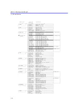
Страница 69: ...ucture and the procedures of operating the menu 3 4 1 Menu Structure The menu is a 3 level hierarchical structure Level 1 Category level Selects categories Level 2 Select level Selects parameters to s...

Страница 70: ...4601 I V Meter Operation Manual 3 4 1 Menu Structure 3 18...

Страница 71: ...o change the parameters at the Input Run level 3 4 2 How to Operate Menu Change the parameters in the menu in according to the following procedure Press The MENU key goes ON Example display Select the...

Страница 72: ...ay Move from the Select level to the Input Run level with Example display Change the parameters at Input Run level with or or by using the rotary knob Example display After changing the parameters pre...

Страница 73: ...ers from the menu Restoring to the factory default settings For information on the initial values and the factory default settings refer to Section 6 6 3 Remote Com mand List 3 5 1 Initializing Parame...

Страница 74: ...ay Press to exit the menu 3 5 2 Restoring to Factory Default Settings Operating procedure Turn OFF the power Turn ON the power while pressing and at the same time Example display Indicates that the 46...

Страница 75: ...parameters 3 6 1 Loading Parameters The setting parameters saved separately in the non volatile memory areas User 0 to User 3 can be loaded For information on how to save the parameters refer to Sect...

Страница 76: ...e menu 3 6 2 Saving Parameters The setting parameters can be saved to the non volatile memory areas User 0 to User 3 separately The 4601 can start up with the parameters saved in User 0 at power ON Fo...

Страница 77: ...splay Press or or rotate the rotary knob to select User 3 Example display Press to save the parameters to User 3 Example display The descriptions of these parameters are as follows User 0 Saves the pa...

Страница 78: ...ing shows the procedure of changing the setting to start the 4601 with the parameters saved in User 0 For information on how to save the parameters to User 0 refer to Section 3 6 2 Saving Parameters O...

Страница 79: ...4601 I V Meter Operation Manual 3 6 3 Auto Parameter Loading at Power ON 3 27 Press or or rotate to select User 0 Saved Example display Press to exit the menu 6 7...

Страница 80: ......

Страница 81: ...unter Select 4 9 Disp Key Test 4 9 Display On Off 4 10 Error Queue 4 10 EXT SIGNAL 4 8 First Value 4 6 GPIB Address 4 9 Header 4 9 Hold Time 4 7 Integ Time 4 7 INTERFACE 4 9 Interface Bus 4 9 Last Val...

Страница 82: ...4601 I V Meter Operation Manual 4 1 Menu Index 4 2 Sweep Type 4 5 SWEEP VALUE 4 6 SYSTEM 4 10 Temp Unit 4 7 Third Value 4 6 TIME 4 7 Trigger Delay 4 7 USB Id 4 9...

Страница 83: ...ange that cannot output the currently set source value 4 2 4 DOWN Key Measurement Range Down Decreases the external voltage measurement range or referenced cell current range by one keys Moves the cur...

Страница 84: ...ction Switches the sampling between AUTO and HOLD The HOLD key goes ON when the sampling is set to HOLD 4 2 9 LIMIT Key Current Limit Setting Switches between the voltage source value screen and the c...

Страница 85: ...tting current limit value 2 Response Sets the voltage source response Extra Fast Sets the voltage source response to extra fast speed Fast Sets the voltage source response to high speed Medium Sets th...

Страница 86: ...3 Last Value Sets the stop value 4 Step Count Sets the step count 2 slope linear sweep 1 Bias Value Sets the bias value 2 First Value Sets the start value 3 Second Value Sets the start value for the...

Страница 87: ...ime Tdr between the external trigger TRIGGER IN signal and the sweep start or between the external trigger and the next step value output E MEASURE Sets the measurement related parameters 1 Memory Rec...

Страница 88: ...signal 3 Signal Width Selects the signal width of Complete Out Sync Out between 10 s and 100 s G PARAMETER Loads or saves the setting parameters 1 Load Loads the setting parameters saved in the non vo...

Страница 89: ...or not On Output Off No output 6 Output Im Data Sets whether the Im data ADC2 measured value is output or not On Output Off No output 7 Output ADC3 Dt Sets whether the ADC3 measured value is output or...

Страница 90: ...ghest level Level 2 2 3 brightness medium level Level 1 1 3 brightness lowest level 3 Buzzer Buzzes when each operation is complete On Turns ON the buzzer Off Turns OFF the buzzer 4 Error Queue Reads...

Страница 91: ...p source mode 4 2 17 TRIGGER Key Measurement Trigger and Sweep Start DC source mode When the sampling is set to AUTO this key is ignored When the sampling is set to HOLD the HOLD key goes ON this key...

Страница 92: ......

Страница 93: ...esponse delay as shown in Figure 5 2 A In addition for micro current 1 A or less measurement use shielded twisted pair cables as shown in Figure 5 2 B CAUTION 1 When the output units are mounted on bo...

Страница 94: ...s corresponding wire size Figure 5 2 Connection with Output Unit 5 1 2 Reference Cell Measurement Terminal The following figure shows the terminal to measure the reference cell current Figure 5 3 Refe...

Страница 95: ...able to the thermocouple connector Tc1 or Tc2 the platinum resistance bulb connec tor Pt1 or Pt2 or the IC sensor connector Ad1 or Ad2 attach the EMC compliant clamp filter as shown in Figure 5 5 or F...

Страница 96: ...wo source modes the sweep source mode that allows easy acquisition of PV I V characteristic curves and the DC source mode that allows checking of system connections or device operations For more infor...

Страница 97: ...ription Operation Remarks Operate ON AUTO Executes con tinuous mea surement with the setting period time Tp Tp Period time Td Measurement delay time Tds Source delay time Tm Measurement time Integrati...

Страница 98: ...n the sampling is set to AUTO Measurement repeats itself with the specified period time The period time is extended if measurement does not finish within the period time b When the sampling is set to...

Страница 99: ...scriptions of the sweep source mode with reverse OFF one way sweep Table 5 3 Operational Descriptions of Sweep Source Mode 1 of 2 Sweep type Operational description Waveform Linear sweep 1SWP Sweeps b...

Страница 100: ...values stored in the memory from the start address to the stop address 1 Sweep type setting Select SWP with the MODE key Select B SWEEP with the MENU key From the parameters in 1 Sweep Type select 1...

Страница 101: ...time Integration time Mea surement data processing time Tcn Operate pro cessing time Trd Trigger delay time HOLD Executes measure ment by trigger input The step count per trigger is 1 Executes measure...

Страница 102: ...le shows the source and measurement timings in the sweep source mode with reverse ON round sweep Sweep type Operational description Waveform Linear sweep 1SWP Sweeps by staircase waveforms of the step...

Страница 103: ...5 7 Basic Source and Measurement Timings Set the measurement delay time Td longer than the settling time Ts to obtain stable measured values Ts Td RTB Waveform Description ON Returns to the bias value...

Страница 104: ...Condition Source mode DC mode Period time Tp 10 ms Condition Source mode DC mode NOTE If the period time is less than 10 ms when the source mode is switched from the sweep mode to the DC mode the per...

Страница 105: ...ource mode DC sweep mode Integration time Tit Time ms Tk time ms Tit Tk ms 50 Hz 60 Hz 50 Hz 60 Hz 5 s 0 005 0 013 0 018 10 s 0 01 0 017 0 027 25 s 0 025 0 027 0 052 50 s 0 05 0 045 0 095 100 s 0 1 0...

Страница 106: ...e resolution The source delay time and the measurement delay time operate with the rounded off values The setting values are displayed on the screen The following table shows the minimum setting value...

Страница 107: ...ation of the actual cable wiring the device characteristics and the required measurement speed Figure 5 8 Settling Time and Measurement Delay Time This section describes how to calculate the 4601 sett...

Страница 108: ...the response is slow or medium Sr and p do not depend on Vs and Vs max Vs max V IL 3mA to 10A range Sr s p s Current limit count value D Response slow medium fast Ext fast 1000 to 3200 50 36 600 to 10...

Страница 109: ...nse slow As the response is slow there is no condition on Vs max Settling time until the source voltage enters within an error of 0 1 when changing by 5 V Ts 5 0 1 6 9 65 499 s NOTE To shorten the set...

Страница 110: ...operation time and improve the life of the relay Therefore setting in the Suspend status is recommended whenever turning OFF the output to change the measurement condition The following figure shows...

Страница 111: ...ng the DUT to low impedance status when the output is OFF The output response speed is faster because the limit value does not change in the Operate status 4 Current limit in Suspend The output in the...

Страница 112: ...between Standby and Operate because relay ON OFF operations are re quired To reduce time and delete these unnecessary relay ON OFF operation the output status is switched between Suspend and Operate...

Страница 113: ...atus are described below Status Effective operation Operate Measurement Suspend HiZ Device replacement LoZ Measurement stop The output status is as follows Sweep mode 0 V in the bias range DC mode 0 V...

Страница 114: ...ce cell external voltage temperature measurement Ir Reference cell current measurement Em External voltage measurement Tc1 Ch1 T type thermocouple measurement Pt1 Ch1 resistance bulb Pt temperature me...

Страница 115: ...I V measurement with the output status kept in Operate In ADC3 measurement temperature measurement Tc1 is performed before and after sweep and reference cell current measurement Ir is performed durin...

Страница 116: ...en the integration time or measurement function range is changed or spot measurement is performed No ADC Function Range Zero code 1 ADC1 Vm Voltage measurement 5 V 300 V AZ10 2 ADC2 Im Current measure...

Страница 117: ...nu and setting 2 Memory Store to ON The measurement memory contents are automatically cleared when 2 Memory Store is switched from OFF to ON In the sweep mode the memory store function automatically t...

Страница 118: ...illate under the influence of the device capacitance or cable inductance The 4601 detects such an oscillation by its output terminals and internal circuits and displays an alarm with measured values I...

Страница 119: ...isplayed however measurements are not guaranteed Thus when the alarm is displayed replace the output unit For information on how to replace the output unit refer to Section 1 3 Output Unit The 4601 is...

Страница 120: ...5 28 Operating procedure Press to select 1 MAINTENANCE from the categories and 6 Reset Counter from the parameter items Example display Press to move to the lower level Example display Press to reset...

Страница 121: ...le and turn the power ON again If the alarm is still generated request a repair service Error code Message Detection timing Description 401 Fan Stopped At any time The rear panel fan stops 402 Over He...

Страница 122: ...tact signal output port setting Select the output port by n 0 to 3 and the output status by v 0 Break 1 Make DSO n Query of output setting Response DSO n v n 0 to 3 v 0 or 1 DSI n Contact signal input...

Страница 123: ...Aviation Electronics Industry Ltd D02 22 26P PKG100 Pin contact 28 to 26 AWG Japan Aviation Electronics Industry Ltd DE C8 J9 F2 1R Junction shell Japan Aviation Electronics Industry Ltd Pin No Signa...

Страница 124: ...ut TTL nega tive pulse 10 s or more 3 Approx 100 open drain Pulled up to 5 V by 10 k Measurement end and period end signal DC source mode Sweep stop or end signal sweep mode SYNC OUT 1 Output Step up...

Страница 125: ...to Table 5 8 and Table 5 9 3 Restriction on the time Thp ext between sweep start and the next trigger signal input In the sweep source mode there is a restriction on setting the time Thp ext between t...

Страница 126: ...erational minimum period of TRIGGER IN signal Condition Sampling HOLD Integration time 5 s Measurement delay 20 s Source delay 10 s at high speed burst operational status 2 2 High speed burst operatio...

Страница 127: ...4601 I V Meter Operation Manual 5 5 3 Restrictions on Using External Trigger 5 35 Example in the DC source mode Example in the sweep source mode...

Страница 128: ...ting the time parameters such as measurement delay and source delay 1 Three unit synchronous operation using SYNC OUT The Operate or Suspend status and the source and measurement timings are synchroni...

Страница 129: ...4601 I V Meter Operation Manual 5 6 1 Synchronous Operation 5 37...

Страница 130: ...a 1 when using more than one 4601 in synchronous operation Slave Tp and Th have restrictions on using the external trigger The first synchronous sweep step has a gap within the Th accurate range Tp in...

Страница 131: ...on Figure 5 12 Parallel Connection CAUTION 1 If the load is opened current flows from the higher to the lower of the set voltage Depending on the settings an overload may be generated 2 If the load is...

Страница 132: ...re If this procedure is not followed an overvoltage alarm may occur Operate procedure No 2 setting voltage PV output voltage 300 V No 1 setting voltage 0 V Set No 2 to Operate Set No 1 to Operate No 2...

Страница 133: ...2 to Operate Set No 1 to Operate No 2 setting voltage 0 V Set the source voltage When setting the output voltage to 300 V or less set the No 2 output voltage When setting the output voltage to 500 V...

Страница 134: ...re units in series If the load is short circuited the maximum applicable voltage will be exceeded causing damage to the 4601 WARNING In series connection use the reference cell terminal the voltage me...

Страница 135: ...thod see Figure 5 14 RTB Return to Bias of the first unit is set to OFF so that the output value does not return to the bias value and stays at the stop value at sweep end The second unit starts sweep...

Страница 136: ...ues to 10 A set as follows No 1 limit value 10 A No 2 limit value 10 2 A When the PV output voltage exceeds 300 V set the output status to Operate according to the following procedure If this procedur...

Страница 137: ...t three or more units in series If the load is short circuited the maximum applicable voltage will be exceeded causing damage to the 4601 WARNING In series connection use the reference cell terminal t...

Страница 138: ...ata sum error 013 Parameter SUM Parameter memory sum error 101 Analog section RST signal ADRST Signal Check 102 Analog section TRIG signal ADTRG Signal Check 111 ADC1 operation IR1 IR2 ratio ADC1 Rati...

Страница 139: ...ADC3 Zero AZ34 201 VSVM 5V ZERO VSVM 5V Zero 202 VSVM 5V FS VSVM 5V Full Scale 203 VSVM 5V FS VSVM 5V Full Scale 204 VSVM 50V ZERO VSVM 50V Zero 205 VSVM 50V FS VSVM 50V Full Scale 206 VSVM 50V FS VSV...

Страница 140: ...y lost 130 Sub CPU communication Sub CPU does not respond 571 Operate relay lifetime Operate Relay Lifetime All the panels light ON Visual check of display Buzzer Check by buzzer sound Panel key Visua...

Страница 141: ...the menu screen finishes after the error log screen is displayed When the ERR or CLS command is executed Not cleared by RST 3 Reading out error logs Press The MENU key goes ON Example display Press on...

Страница 142: ...Meter Operation Manual 5 8 Error Log 5 50 Press Rotate the rotary knob or press or to change the error log number and read error descriptions The following is an example of Undefined header Example di...

Страница 143: ...erational Principles 5 51 5 9 Operational Principles 5 9 1 Block Diagram HiLimit DAC Src DAC LoLimit DAC ADC1 A1 A2 A3 HiLmt Src LoLmt Switching circuit A4 RS2 A6 SW2 VM IM RS1 A5 A7 HI SENSE HI OUTPU...

Страница 144: ...is a DA converter for current limiter on the HI side and HiLmt A2 is an error amplifier for current limiter on the HI side Likewise LoLimitDAC and LoLmt A3 work as current limiters on the LO side Sou...

Страница 145: ...4 mA at the negative side source The external voltage measurement circuit Em switches the range between 30 mV 300 mV and 3 V by switching the gain of the high input impedance amplifier A12 between x10...

Страница 146: ......

Страница 147: ...memory The selected interface does not change when the unit is turned off or the interface is reset 2 A unique unit address is set in the interface If multiple instruments are connected to the USB in...

Страница 148: ...measured values The remote commands are the same as with USB General Specifications Standard IEEE 488 2 Code ASCII code Logic level Logical 0 High 2 4 V min Logical 1 Low 0 4 V max Table 6 1 Interface...

Страница 149: ...of each device Ensure that all devices on the bus are turned on If any device on the bus is not turned on the system may not operate correctly 4 Connecting and disconnecting cables Turn off all device...

Страница 150: ...mat from ASCII to binary Operating procedure Press The MENU key goes ON Example display Press or or rotate the rotary knob to select H INTERFACE from the categories Example display Press to move to th...

Страница 151: ...ss by using the numeric keypad Example display Press to move to the upper level Example display Press or or rotate the rotary knob to select 4 Output Format from the parameters Example display Press t...

Страница 152: ...SB2 0 Full Speed Connectors USB B type female Identifier ID USB ID settable from 1 to 127 Remote Local Available Input commands Function setting and query with ASCII character string commands Output f...

Страница 153: ...ress from 01 to 12 Operating procedure Press The MENU key goes ON Example display Press or or rotate the rotary knob to select H INTERFACE from the categories Example display Press to move to the lowe...

Страница 154: ...ess or or rotate the rotary knob to select 2 USB Id Example display Press to move to the lower level Example display Press or to select the digit and rotate the rotary knob to change the value Or dire...

Страница 155: ...event register latches and maintains the status for each event It may also hold changes Once the register is set it remains set until it is read out by a query or cleared by CLS Data cannot be written...

Страница 156: ...Set to 0 when Error Queue is read and becomes empty 3 QSB Questionable Summary Bit ON Set to 1 when any of Questionable Event Register events occurs and the bit is set to 1 if the corresponding bit of...

Страница 157: ...red by CLS except that MAV is not cleared if data exists in the output buffer Not cleared even if read by STB Conditions in which the Service Request Enable Register is cleared Cleared when the power...

Страница 158: ...executed Table 6 4 Standard Event Status Register bit Name Description 0 OPC Operation Complete ON Set to 1 when all operations are complete after receiving the OPC command 1 Not in use Always set to...

Страница 159: ...or ON Set to 1 when fan stop or overheat of the booster unit is detected 6 OVV Over Voltage ON Set to 1 when overvoltage is detected 7 Not in use Always set to 0 8 Not in use Always set to 0 9 RSN Rea...

Страница 160: ...to 0 3 Not in use Always set to 0 4 Not in use Always set to 0 5 Not in use Always set to 0 6 Not in use Always set to 0 7 Not in use Always set to 0 8 CAL Summary of Calibration ON Set to 1 when the...

Страница 161: ...asured values to be output can be set by using the OTM command or from the MENU This setting is not initialized by RST or RINI Output No output OTM designated value ADC3 measured value ADC2 measured v...

Страница 162: ...n multiple data sets are output the data sets are separated by commas Format Description ASCII Outputs one value as a 12 byte header OFF or 15 byte header ON ASCII character string The internal proces...

Страница 163: ...put on the sub headers of temperature measurement Function Target Main header ADC1 Vm Vm VM ADC2 Im Im IM ADC3 Ir Reference cell Isc IR Em EXT DCV EM Tc1 Ch1 thermocouple T TA Pt1 Ch1 PT100 PA Ad1 Ch1...

Страница 164: ...ddddd E 03 30 mA dd dddd E 03 300 mA ddd ddd E 03 3 A d ddddd E 00 10 A dd dddd E 00 ADC3 Ir 3 mA d ddddd E 03 30 mA dd dddd E 03 300 mA ddd ddd E 03 Em 30 mV dd dddd E 03 300 mV ddd ddd E 03 3 V d d...

Страница 165: ...lock delimiter The block delimiters can be specified by using the following commands NOTE When the binary output format is selected EOI is specified regardless of the block delimiter settings Block de...

Страница 166: ...all the bits of the mantissa and the exponent to 0 The mantissa and the exponent are represented in binary The sign bit 0 is for positive and 1 is for negative When the binary output format is select...

Страница 167: ...ble type consists of 8 bytes System BitConverter ToDouble byteArray i ToString Converts the byte array to double VBA Declare Sub CopyMemory Lib kernel32 Alias RtlMoveMemory Destination As Any Source A...

Страница 168: ...al structure Placing a question mark right after the header forms a query command 2 Space blank character One or more spaces can be used Spaces may be omitted 3 Data When a command requires multiple d...

Страница 169: ...t Some commands can add units to the data when the data is input Integer type NR1 format Fixed point type NR2 format Floating point type NR3 format NOTE When numeric data is expressed in exponent form...

Страница 170: ...nd list Parameter enclosed in can be omitted Parameters enclosed in are single delimited data items The Operation column shows whether each command is acceptable or not in the Operate status OPR and t...

Страница 171: ...IR3 300 mA range LIR4 3 A range LIR5 10 A range LIR Response LIRX0 to LIRX5 for the optimal range LIR 0 to LIR 5 for the fixed range Limit value LMI data1 data2 Current limit value setting 100 mA data...

Страница 172: ...olution 100 s fixed THD Response THDdddd d Trigger delay TRD time Trigger delay setting Unit ms 0 ms Setting range 0 to 6000 0 ms Resolution 100 s fixed TRD Response TRDdddd d Response FL0 SLOW FL1 ME...

Страница 173: ...ng count 1 to 2000 1 If all the settings are omitted set the sweep type only However it is not allowed to omit each value separately SFX Response SFX lvl cnt lvl d ddddE d 1 cnt dddd Memory sweep SMD...

Страница 174: ...cnt cnt dddd Reverse mode SV0 OFF SV1 ON SV Response SV0 or SV1 Sweep stop SWSP Stops the sweep Trigger TRG Sweep start trigger Measurement trigger Mea sure ment Function ADC3 measurement F0 Measurem...

Страница 175: ...format described in Section 6 5 4 ASCII Output Format SPM 9 Pt2 or Ad2 However the header is always output in the ASCII format NOTE Not executable in the DC source mode Measurement buffer memory ST0...

Страница 176: ...mperature unit TPU0 Temperature unit C TPU1 Temperature unit F TPU2 Temperature unit K TPU Response TPU0 to TPU2 Resistance bulb RTD0 Pt100 RTD1 JPt100 RTD Response RTD0 to RTD1 System User parameter...

Страница 177: ...nd output OP0 STBY In signal input IN OP1 OPR STBY IN signal input IN OP2 OPR SUS In signal input IN OP3 Operate Out signal output OUT OP Response OP0 to OP3 Synchronous control signal output setting...

Страница 178: ...mat output 9 FMT Response FMT0 or FMT1 Header output OH0 OFF OH1 ON NOTE The header is not output even if it is set to ON in the binary output mode 6 OH Response OH0 or OH1 Output target data OTM n Sp...

Страница 179: ...PC Response 1 after all operations completed WAI Waits until all operations are complete GPIB only 9 Calibra tion Calibration data XINI Initializes the calibration data area for calibration execution...

Страница 180: ...he DMM data input mode XD data data DMM reading data XADJ Switches to the calibration data fine adjustment mode XNXT Moves on to the next calibration Item Command Description Default Operation During...

Страница 181: ...ates DC voltage in the DC source mode and measures Voc open circuit voltage and Isc short circuit current Example 2 1 The 4601 executes 99 step linear sweep in the sweep source mode receives a SRQ tha...

Страница 182: ......

Страница 183: ...l ibration 4 of 4 7 3 Test Method Execute the performance test under the following conditions in a location free of dust vibration noise or other adverse conditions Temperature 23 C 5 C Relative humid...

Страница 184: ...een the source value and the measured current of the 4601 is within the accuracy described in Chapter 9 SPECIFICATIONS 6 Change the current limit value from 3 2 mA to 10 2 A change the source value of...

Страница 185: ...n Figure 8 2 f 2 Set the 4601 to the DC source mode AUTO sampling and integration time of 200 ms 3 Set ADC3 measurement to the Pt1 or Pt2 function 4 Set the output status to Operate 5 Set the resistan...

Страница 186: ...ECIFICATIONS The temperature at each voltage is as follows 7 3 9 External Voltage Measurement Test 1 Connect the 4601 and a voltage source standard as shown in Figure 8 4 j 2 Set the 4601 to the DC so...

Страница 187: ...ded cables such as A01035 A01047 etc 8 1 2 Precautions 1 Use an AC power supply with the specified voltage 2 Execute calibration under the following conditions in a location free of dust vibration noi...

Страница 188: ...n bath Figure 8 1 Connections for Calibration 1 of 4 a Voltage source and voltage measurement calibration 6581 4601 Red Red Black Black A01035 etc b Current Measurement Calibration 300 A to 300 mA ran...

Страница 189: ...limit calibration Black Black Red Red 4601 CELL 4601 Current source standard E E I I e Reference current measurement calibration f Pt measurement calibration Plug Product equivalent to PHOENIX CONTAC...

Страница 190: ...equivalent to PHOENIX CONTACT MC1 5 5 ST 3 81 Current source standard 1 5 4601 h Thermocouple measurement calibration Plug Product equivalent to LABFACILITY IM T M 4601 Voltage source standard i Refe...

Страница 191: ...4601 I V Meter Operation Manual 8 2 Connections 8 5 Figure 8 4 Connections for Calibration 4 of 4 j External voltage measurement calibration Voltage source standard 4601...

Страница 192: ...llow ing table Table 8 2 Calibration Tolerance Ranges 1 Voltage source voltage measurement current measurement terminal Source calibration Voltage measurement calibration Voltage source calibration VS...

Страница 193: ...000 mA 0 5d 3 mA 0 00000 mA 2d 3 000 mA 0 5d 3 00000 mA 2d 30 mA 00 00 mA 0 5d 30 00 mA 0 5d 30 mA 00 0000 mA 2d 300 mA 000 0 mA 0 5d 30 0000 mA 2d 300 0 mA 0 5d 3 A 0 000 A 0 5d 300 mA 000 000 mA 5d...

Страница 194: ...urement calibration Em Range Calibration point Tolerance specification digit 30 mV 00 0000 mV d 30 0000 mV d 300 mV 000 000 mV d 300 000 mV d 3 V 0 00000 V d 3 00000 V d Reference cell current measure...

Страница 195: ...t Tc1 50 mV 00 0000 mV 0d 50 0000 mV d Tc2 50 mV 00 0000 mV d 50 0000 mV d Thermocouple reference junction temperature calibration Tc1 Tc2 Range Calibration point Tolerance specification digit Tc1 0 C...

Страница 196: ...Calibration Procedure 8 10 8 4 Calibration Procedure 8 4 1 Calibration Operation The 4601 is calibrated by using the remote commands through the GPIB or USB interface Figure 8 5 to Figure 8 11 shows...

Страница 197: ...4601 I V Meter Operation Manual 8 4 1 Calibration Operation 8 11 Calibration procedure 1 The following figure shows the overall flow of calibrations Figure 8 5 Calibration Procedure 1...

Страница 198: ...ion Manual 8 4 1 Calibration Operation 8 12 Calibration procedure 2 The following figure shows the flow of voltage source calibration Connect the 4601 to the DMM as shown in Figure 8 1 a Figure 8 6 Ca...

Страница 199: ...Manual 8 4 1 Calibration Operation 8 13 Calibration procedure 3 The following figure shows the flow of voltage measurement calibration Connect the 4601 to the DMM as shown in Figure 8 1 a Figure 8 7...

Страница 200: ...14 Calibration procedure 4 The following figure shows the flow of current measurement calibration Connect the 4601 to the standard as shown in Figure 8 1 b in the 300 A to 300 mA range or Figure 8 1...

Страница 201: ...Operation Manual 8 4 1 Calibration Operation 8 15 Calibration procedure 5 The following figure shows the flow of current limit calibration Connect the 4601 as shown in Figure 8 2 d Figure 8 9 Calibrat...

Страница 202: ...in Figure 8 2 e for Ir measurement calibration Figure 8 4 j for Em mea surement calibration Figure 8 3 h for T measurement calibration Figure 8 2 f for Pt measurement cal ibration or Figure 8 3 g for...

Страница 203: ...ration Operation 8 17 Calibration procedure 7 The following figure shows the flow of reference junction temperature calibration Connect the 4601 to the 0 C standard calibration bath as shown in Figure...

Страница 204: ...latile memory by XWR 6 Finish the calibration mode by CAL0 8 4 2 2 Voltage Source Calibration The procedure of voltage source calibration is described according to Figure 8 6 Calibration Procedure 2 1...

Страница 205: ...D data 9 Read out and check the measurement data 10 Move to the next step by XNXT 11 Set calibration mode to Standby by SBY 8 4 2 4 Current Measurement Calibration The procedure of current measurement...

Страница 206: ...XILH Current LO limit XILL Calibrate the current LO limit first and the current HI limit second 3 Select the range 300 A range XR0 3 mA range XR1 30 mA range XR2 300 mA range XR3 3 A range XR4 10 A r...

Страница 207: ...XPT1 XPT2 AD590 measurement XAD1 XAD2 As for the Ir or Em measurement function select the range 3 mA range XR1 30 mA 30 mV range XR2 300 mA 300 mV range XR3 3 V range XR4 3 Enter the DMM data input mo...

Страница 208: ...dure 7 The ADC3 measurement function should be set to T thermocouple measurement 1 Set the calibration mode to Operate 2 Select the command depending on either Tc1 or Tc2 function Tc1 function XRJ1 Tc...

Страница 209: ...to 0 1 A and 10 2 A The measurement resolution with the integration time of 500 s or less is as follows Overall accuracy Voltage source voltage measurement Range Source range Setting resolution Measu...

Страница 210: ...100 mA 0 15 7 mA 500 A Measurement range Integration time 5 s 10 s 25 s 50 s 100 s 250 s 500 s 1 ms 2 5 ms 5 ms 10 ms Voltage measurement 5 V 300 300 100 30 20 20 20 10 10 5 5 50 V 300 300 100 30 20 2...

Страница 211: ...k current As for sink operation with the output voltage of 0 V to 1V the remote sensing voltage becomes 1 V when the result of the above formula is 1 V or higher Maximum input voltage 320 V 3 V peak m...

Страница 212: ...surement and current measurement with the integration time of 10 ms or less Measurement range Integration time 5 s 10 s 25 s 50 s 100 s 250 s 500 s 1 ms 2 5 ms 5 ms 10 ms 30 mV 2000 1500 1000 1000 500...

Страница 213: ...resolution with the integration time of 500 s or less is as follows The following full scale errors digits are added in measurement with the integration time of 10 ms or less Measurement range Measur...

Страница 214: ...above Maximum allowable input voltage 36 V peak terminal terminal 310 V peak terminal chassis The measurement resolution with the integration time of 500 s or less is as follows The following full sca...

Страница 215: ...ution with the integration time of 500 s or less is as follows The following full scale errors digits are added in voltage measurement and current measurement with the integration time of 10 ms or les...

Страница 216: ...ep step 1999 steps Maximum measurement points 2000 points Maximum sweep memory 2000 data Measurement data memory 4000 data 3 Measurement speed 50 s point to 6 s point sweep source measurement mode Lim...

Страница 217: ...with th minimum measurement source delay time Setting time Mode Minimum step time Sweep 50 s DC 5 ms Setting time Setting range Minimum resolution Setting accuracy Source delay time 0 010 ms to 5999 8...

Страница 218: ...isplay Dot matrix vacuum fluorescent display Power supply AC power 100V 120V 220V 240V User selectable Line frequency 50 Hz 60 Hz Power consumption 230 VA or less Dimensions Approx 424 width 132 heigh...

Страница 219: ...not output the set source value Cause Solution It is in Standby or Suspended status Set Operate and check that the OPR indicator on the front panel is ON Cause Solution The source value is set to 0 V...

Страница 220: ...onnected cable Verify the cables with a tester If in error replace it Cause Solution A cable is connected to a wrong terminal Check cable connections again Cause Solution The induction noise scatters...

Страница 221: ...communication error Panel memory error 003 VFD module communication error VFD module error 004 RAM read write error RAM read write failed 005 Analog section communication error Communication error 008...

Страница 222: ...t error ADC2 Zero AZ20 143 ADC3 operation zero measurement AZ30 test error ADC3 Zero AZ30 144 ADC3 operation zero measurement AZ31 test error ADC3 Zero AZ31 145 ADC3 operation zero measurement AZ32 te...

Страница 223: ...perate Relay Lifetime 801 1999 Sweep step count Over 1999 steps 802 Sweep data over range Sweep Value Over Range 823 DC timer condition error Not satisfy Tp Td 300 s Tp Td 0 3 ms DC 824 SWEEP timer co...

Страница 224: ...tandby Source mode Sweep Step count 100 IT 1 PLC 20 ms Other Default values 101 117 In Suspend HiZ 9 25 In Suspend LoZ 8 24 Suspend SUS OPR SUS LoZ Source mode DC IT 1 PLC 20 ms Other Default values 8...

Страница 225: ...27 IT5 12 27 IT6 12 29 IT7 14 30 IT8 18 35 IT9 26 41 IT10 41 58 IT11 71 88 IT12 131 148 IT13 311 328 IT14 611 628 Time Parameter Trigger delay TRD data 5 to 6 22 to 25 Hold time THD data 5 to 6 22 to...

Страница 226: ...g the data output from the memory to GPIB by the RDT command Condition Sampling internal trigger Integration time 5 s Output data Vm Im ADC3 measured value Reading starts after receiving SRQ that indi...

Страница 227: ...and data read Condition Spot measurement integration time 1 PLC 20 ms Spot measurement GPIB USB SPM 1 Vm 48 ms 66 ms SPM 2 Im 48 ms 66 ms SPM 3 Ir 58 ms 77 ms SPM 4 Em 61 ms 84 ms SPM 5 Tc1 177 ms 13...

Страница 228: ...g time Time between external trigger input and source value change For the time from when the source value changes to when the source value settles refer to Section 5 2 6 Settling Time Condition Sampl...

Страница 229: ...TE This drawing shows external dimensions of this instrument The difference in products and options used can cause a change in the appearance of the instrument DIMENSIONAL OUTLINE DRAWING DIMENSIONAL...

Страница 230: ......

Страница 231: ...7 1 Counter Select 4 9 Current Limit Calibration 8 20 Current Limit Detection 3 7 5 26 Current Measurement Calibration 8 19 CURSOR Key Cursor Moving 4 3 CURSOR Section 2 1 2 5 D DATA ENTRY Keys Source...

Страница 232: ...22 Measuring Instruments Necessary for Calibration 8 1 Measuring Instruments Necessary for Performance Test 7 1 Mem Save Clear 4 7 Memory Clear 4 7 Memory Data Set 4 7 Memory Recall 4 7 Memory Store 4...

Страница 233: ...etting Time 9 9 Signal Width 4 8 SOURCE 4 5 Source and Measurement Functions 9 8 Source Delay 4 7 SOURCE LIMIT Section 2 1 2 2 Source Measurement Function 5 18 Source Mode 5 4 Source Range 5 18 SPECIF...

Страница 234: ...6 6 USB Id 4 9 USB Overview 6 6 USB Specifications 6 6 Using Interface 6 1 V Voltage Measurement Terminal 8 8 9 3 Voltage Source Calibration 8 18 Voltage Source Voltage Measurement Current Measuremen...

Страница 235: ...ill be a period of one year commencing on the delivery date of the Product 3 If the Product is found to be defective during the Warranty Period ADC CORPORATION will at its option and in its sole and a...

Страница 236: ...ANTICIPATED PROFITS OR REVENUES IN ANY AND ALL CIRCUMSTANCES EVEN IF ADC CORPORATION HAS BEEN ADVISED OF THE POSSIBILITY OF SUCH DAMAGES AND WHETHER ARISING OUT OF BREACH OF CONTRACT WARRANTY TORT INC...

Отзывы: