U
SER
M
ANUAL
HRU-419
HiGain REM UNIT
L
DS1
REM
OS
LB
LOC
LP1
CODE
LP2
FRM
NET
CI
HDSL
B8ZS
AMI
BPV
OK
MAR
ES
RS 232
DCE
ESF
SF
ERR
RS
232
HRU-419 HiGain Remote UnitProduct Catalog: 150-419-100-03CLEI: T1L2CCLAAA
Страница 1: ...19 HiGain REM UNIT L DS1 REM L O S L B LOC LP1 CODE LP2 FRM NET CI HDSL B8ZS AMI BPV OK MAR ES RS 232 DCE OK MAR ES ESF SF ERR R S 2 3 2 D C E HRU 419 HiGain Remote Unit Product Catalog 150 419 100 03...
Страница 2: ...arks or registered trademarks of their respective companies Disclaimer of Liability Information contained in this document is company private to ADC DSL Systems Inc and shall not be modified used copi...
Страница 3: ...ppendix B Abbreviations on page 51 Notes provide information about special circumstances Genenral cautions indicate the possibility of personal injury product failure or equipment damage if instructio...
Страница 4: ...transit immediately report the extent of damage to the transportation company and to ADC DSL Systems Inc Order replacement equipment if necessary Check the packing list to ensure complete and accurate...
Страница 5: ...______________________________________ 11 Inspecting Your Shipment 11 Installing the HRU 419 12 Connecting to a Maintenance Terminal 13 Card edge pinout connector 15 The HRU 419 Circuit Board 16 The M...
Страница 6: ...Conditions 46 HAIS Set to 1 Loop 46 HAIS Set to 2 Loops 46 Using the Loopback LB Button 46 Appendix A Technical Specifications _______________________48 Functional Description 49 Operational Capabilit...
Страница 7: ...mote Terminal Log in Screen 21 Figure 10 Remote Terminal Main Menu 21 Figure 11 View Span Status Screen for Non Doubler Applications 24 Figure 12 Span 3 Status for Two Doublers Application 26 Figure 1...
Страница 8: ...helf and Mounting Hardware Compatibility 9 Table 6 HRU 419 Card Edge Connector Pinouts 16 Table 7 Maintenance and Remote Terminal Navigational Keys 22 Table 8 Maintenance and Remote Terminal Menus 23...
Страница 9: ...helf and the HRU is housed in a remote enclosure at the Customer Premises Equipment CPE Optional HDUs provide the ability to double or even triple the distance range for customer applications located...
Страница 10: ...d loopback and Alarm Indication Signal AIS Line or local power options Optional sealing current Supports three span line powering CPE current monitor test points available on PC board Lightning and po...
Страница 11: ...n loss measurement data add 3 dB for each bridged tap and 1 dB for each cable gauge change The HiGain systems can operate with any number of other T1 Plain Old Telephone Service POTS or other HiGain s...
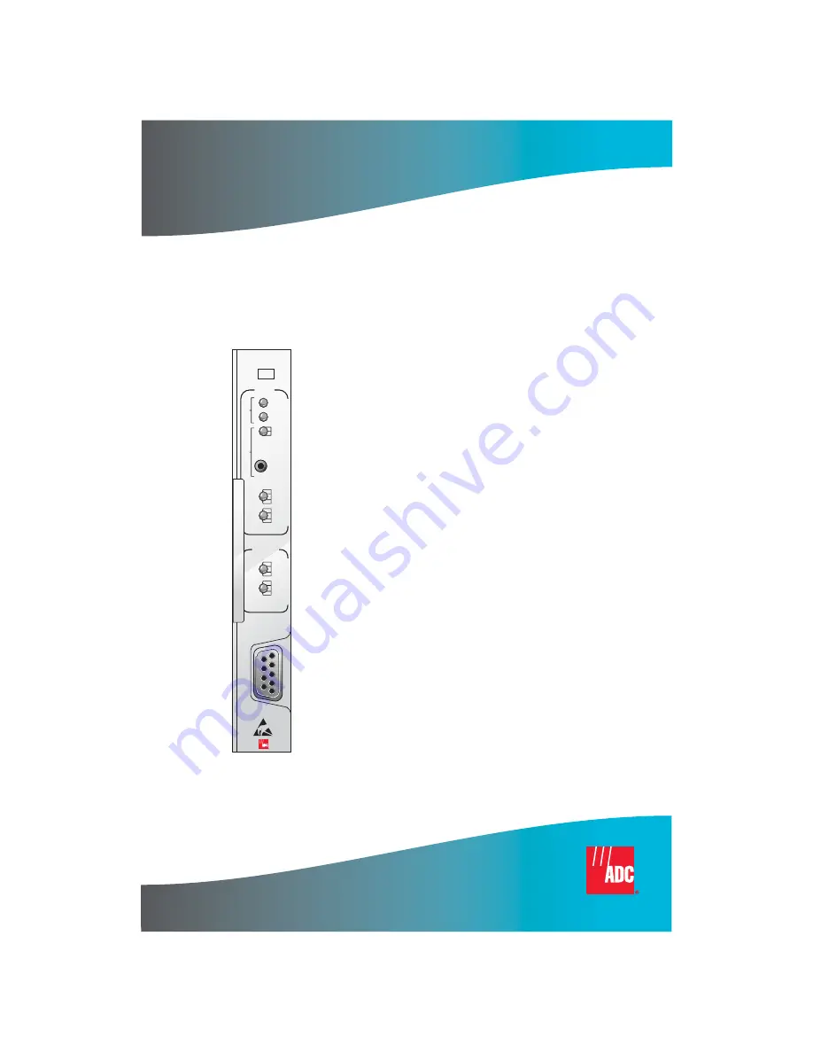
Страница 12: ...panel components and Table 4 describes the status conditions indicated by the LEDs Figure 2 HRU 419 Front Panel HRU 419 HiGain REM UNIT L DS1 REM L O S L B LOC LP1 CODE LP2 FRM NET CI HDSL B8ZS AMI B...
Страница 13: ...oopback LB Button on page 46 Code LEDs Provide indications for line code options see Table 3 on page 6 and Table 4 on page 7 Framing LEDs Provides indications for framing patterns see Table 3 on page...
Страница 14: ...t to Alternate Mark Inversion AMI BPV Indicates that a Bipolar Violation BPV is received at the remote s DS1 input FRM LEDs Indications for framing patterns ESF Displays ESF framing SF Displays SF fra...
Страница 15: ...ped back to the NET Off No NET loopbacks are active CI On Lights yellow when the HRU is in a loopback state when the signal from the CI is being looped back to the CI Off No CI loopbacks are active B8...
Страница 16: ...blers ES Blinks red every second when one HDSL CRC error is detected on Loop 1 from the upstream module LP2 OK Blinks green when HDSL Loop 2 is synchronizing with the HLU Lights green when HDSL Loop 2...
Страница 17: ...dustries 3192 9F Alarm Card Larus 1185 28 slot connectorized Larus 1184 Alarm Card Charles Industries 3192 WR 28 slot wire wrap Charles Industries 343 00 12 14 slot wire wrap Charles Industries 319 02...
Страница 18: ...ent towards all versions of the HLU over the 2 HDSL pairs Jumper JP1 shown in Figure 7 on page 17 allows the sealing current to be enabled or disabled see The HRU 419 Circuit Board on page 16 Reversed...
Страница 19: ...Gain Mini Doublers Model HDU 437 and HDU 439 technical practice INSTALLATION This section provides information on inspection and installation of the HRU 419 INSPECTING YOUR SHIPMENT When you receive t...
Страница 20: ...308 To install the HRU 419 Figure 3 Set the user options as described in the following 1 Slide the HRU 419 into the card guides for the desired slot then push the unit into the enclosure until it tou...
Страница 21: ...ew only Maintenance and Remote Terminal menus the Set Clock option is the only user configurable option on the HRU 419 Figure 4 shows the HRU 419 DB 9 RS 232 I O Figure 4 DB 9 RS 232 I O The maintenan...
Страница 22: ...Installation 150 419 100 03 14 September 25 1998 HRU 419 List 1 Figure 5 Connecting the HRU 419 to a Maintenance Terminal Card shelf ASCII terminal Interface cable 9 pin COM port HRU 419...
Страница 23: ...mber 25 1998 15 CARD EDGE PINOUT CONNECTOR The HRU 419 card edge connector pinout orientation is shown in Figure 6 Table 6 provides the card edge connector pinouts Figure 6 HRU 419 Card Edge Connector...
Страница 24: ...in Signal Description Pin Signal Description A DS1_T_TIP DS1 Transmit Tip 1 DS1_T_RING DS1 Transmit Ring B DS1_R_TIP DS1Receive Tip 1 2 DS1_R_RING DS1 Receive Ring E 5 CIRCUIT GND Circuit Ground F HDS...
Страница 25: ...9 100 03 Installation HRU 419 List 1 September 25 1998 17 Figure 7 HRU 419 Circuit Board Connections for User Options JP2 RLEV TLOS LB I CPE JP3 JP4 0 1 3 3 3 1 1 15 DIS 0 60 ENBL SCURR JP1 2 1 JP2 JP...
Страница 26: ...t signal level from the HRU towards the NI level to 15 dB This setting is recommended when the HRU functions as the NID To set the RLEV do one of the following To set the T1 output signal level to O d...
Страница 27: ...nable the TLOS LB move the switch to ENA To disable the TLOS LB move the switch to DIS I CPE JP4 The I CPE switch allows you control the current settings for the interface at the customer premises equ...
Страница 28: ...rence menu you must deselect Show Scroll Bars and Use Function Arrow and Ctrl Keys for Windows A hidden G selection is available from the Maintenance Terminal Main menu if you are using an HLU 231 Lis...
Страница 29: ...9 Remote Terminal Log in Screen Figure 10 Remote Terminal Main Menu HI GAIN HLU 419 REMOTE TERMINAL MAIN MENU ver V2 2L 002D CIRCUIT ID PairGain A VIEW SPAN STATUS C SYSTEM SETTINGS E VIEW PERFORMANC...
Страница 30: ...mote Terminal menus use two different means of selecting an option Press the key indicated to the left of the option Press the letter of the option name shown in parenthesis Table 7 Maintenance and Re...
Страница 31: ...pans 1 2 and 3 for two doubler applications Set Clock Allows you to set both the time and the date parameters at the HLU and to update the same settings at the HRU 419 System Settings Allows you to vi...
Страница 32: ...the Maintenance Terminal Main menu to open the View Span Status screen Figure 11 View Span Status Screen for Non Doubler Applications You can do the following Press to return to the previous menu Pres...
Страница 33: ...s to update current values Press to view the next available span One Doubler Span 2 Status For one doubler configurations Span 2 is the span between the first doubler HDU1 and the HRU 419 Press to vie...
Страница 34: ...ible loopbacks and their descriptions SPAN 3 STATUS HDU2 ver3 0 00FF HRU ver4 0 00FF TIME 05 22 36 DATE 06 11 97 Circuit ID PairGain ALARMS NONE LOOPBACK OFF HDU2 HRU HDSL 1 HDSL 2 HDSL 1 HDSL 2 cur m...
Страница 35: ...gnal than the 196 kHz loss INS Loss Indicates the approximate attenuation of the HDSL loop at 196 kHz It is generated by multiplying the pulse attenuation by 1 25 PPM Offset Indicates the relative off...
Страница 36: ...T1 interface LOSW Loss of Sync Word One of the HDSL loops has lost synchronization H1ES HDSL Loop 1 Errored Seconds Loop ones CRC have exceeded the ES threshold H2ES HDSL Loop 2 Errored Seconds Loop t...
Страница 37: ...rds network initiated from CO network by intelligent office repeater code or by pressing both the HLU Mode and Sel front panel pushbuttons CLOC Customer Local Loopback Loopback at HRU local towards CI...
Страница 38: ...r format of hh mm ss setting the seconds is optional then press The New Date field displays Set Date To set the system date type the month day and year in a mm dd yy format then press The system date...
Страница 39: ...Figure 14 System Settings Screen Table 12 lists the System Settings fields and descriptions C SYSTEM SETTINGS TIME 05 34 58 DATE 06 18 97 EQUALIZATION 399 SMART JACK LPBK ENABLE SPECIAL LPBK A11LB POW...
Страница 40: ...face ZBTSI mode An Off setting tells the system that the ESF frame is operating in its normal non ZBTSI mode ES Alarm THRES Indicates whether the ESAL threshold is set to either None 17 or 170 Loopbac...
Страница 41: ...n Press to exit D Date 06 18 97 PERFORMANCE DATA CIRCUIT ID ERRORED SECONDS UNAVAILABLE SECONDS DS1 HDSL 1 HDSL 2 HLU HRU HLU HRU HLU HRU 01 45 000 000 000 000 000 000 000 000 000 000 000 000 02 00 00...
Страница 42: ...00 000 000 000 000 000 000 000 000 000 000 000 02 15 000 000 001 000 001 000 001 000 001 000 001 000 02 30 000 000 000 000 000 000 000 000 000 000 000 000 02 45 000 000 000 000 000 000 000 000 000 000...
Страница 43: ...00 000 000 000 05 00 000 000 000 000 000 000 000 000 000 000 000 000 05 15 000 000 000 000 000 000 000 000 000 000 000 000 05 30 000 000 000 000 000 000 000 000 000 000 000 000 E xit P revious N ext S...
Страница 44: ...on format is ES UAS for the HLU and the HRU 419 DS1 signal and ES UAS for the HLU and HDU1 over both HDSL Loop 1 and HDSL Loop 2 You can do the following Press to view the previous screen Press to vie...
Страница 45: ...y screen for doubler applications Press from the Remote Terminal Main menu to view the Span 1 Performance Data screen for one doubler Span1 and Span 2 Performance History E Time 05 58 43 7 DAY HISTORY...
Страница 46: ...LU HRU 06 04 00000 00000 00000 00000 00000 00000 00000 00000 00000 00000 00000 00000 06 05 00000 00000 00000 00000 00000 00000 00000 00000 00000 00000 00000 00000 06 06 00000 00000 00000 00000 00000 0...
Страница 47: ...ubler applications as well F Time 00 16 55 7 DAY HISTORY CIRCUIT ID SPAN 1 ERRORED SECONDS UNAVAILABLE SECONDS DS1 HDSL 1 HDSL 2 HLU HRU HLU HRU HLU HRU 01 26 00000 00000 00000 00000 00000 00000 00000...
Страница 48: ...Span 1 LOSW HDSL1 First and last instance of LOSW on HDSL1 Current condition number of alarms Span 1 LOSW HDSL2 First and last instance of LOSW on HDSL2 Current condition number of alarms Span 1 ES HD...
Страница 49: ...ignal is returned to the sending device after passing through a data communications link or network This allows you to compare the returned signal with the transmitted signal and to determine if there...
Страница 50: ...owards customer Loopbacks towards network CI AIS AIS AIS NREM TLOS HRU 419 HRU 419 HRU 419 HDSL HDSL HDSL HDSL HDSL HLU HLU HLU CREM AIS AIS SMJK CLOC HRU 419 HDSL HLU AIS HLU 4in7 3in7 5in7 2in5 LOGI...
Страница 51: ...DSX signal is looped back to the DSX at the HLU Network Doubler Loopback 1 NDU1 Loopback at first doubler towards network initiated by HLU Network Doubler Loopback 2 NDU2 Loopback at second doubler t...
Страница 52: ...there is a problem in the HRUand an HRU Pre Loopback Fail condition occurs This terminates the loopback test and returns the HRU to its unlooped normal state This indicates a defective HRU Pre loop Pa...
Страница 53: ...mer if enabled expires When the HRU is in its AIS DIS SmartJack metallic loop back state its T1 input LOS Code and Frame monitoring circuits are connected to the network s signal which is being looped...
Страница 54: ...ately 16 dB of loss at 200 kHz can remain in sync with one conductor open Since the loop is still in sync no LOSW condition occurs However the margin on a one conductor loop drops approximately 5 to 1...
Страница 55: ...t the HLU unit is in its network loopback state 6 If the test passes the problem is in the cable pair or the HRU If it fails the problem is at the CO 7 If the I CPE 60 mA current option is set to 60 m...
Страница 56: ...ht 0 5 lb 0 23 kg Power Consumption 4 5 W with I CPE set to 0 6 3 W with I CPE set to 60 mA Maximum Provisioning Log 35 dB at 196 kHz 135 Electrical Protection Secondary surge and power cross protecti...
Страница 57: ...90 026R7 SONET Committee Report Line Form AMI B8ZS or ZBTSI Frame Form ESF SF or unframed Line Clock Rate Internal Stratum 4 clock FUNCTIONAL DESCRIPTION This section describes the functions of the H...
Страница 58: ...jumper switch set to 0 and 6 3 W with the I CPE jumper switch set to 60 Caution should be used when the HRU is used to power Channel Service Units CSUs Some CSUs require more output voltage than the 3...
Страница 59: ...tion CI Customer Interface CPE Customer Premises Equipment CRC Cyclic Redundancy Check CSA Carrier Service Area CSU Channel Service Unit DCE Data Circuit Terminating Equipment HDSL High bit rate Digit...
Страница 60: ...tember 25 1998 HRU 419 List 1 NID Network Interface Device POTS Plain Old Telephone Service RLEV Receive Level SCURR Sealing Current S N Signal to Noise SPLB Special Loopback TLOS Transmit Loss of Sig...
Страница 61: ...0 USA and Canada 952 917 3000 Complete Solutions from concept to installation Network Design and Integration Testing System Turn Up and Testing Network Monitoring upstream or downstream Power Monitori...
Страница 62: ...turn Department 800 366 3891 extension 73748 or 952 917 3748 Fax 952 917 3237 Email repair return adc com ADC Return Material Authorization RMA number and instructions must be obtained before returnin...
Страница 63: ...ference at his own expense LIMITED WARRANTY Product warranty is determined by your service agreement Contact your sales representative or Customer Service for details MODIFICATIONS Any changes or modi...
Страница 64: ...ystems Inc 14402 Franklin Avenue Tustin CA 92780 7013 Tel 714 832 9922 Fax 714 832 9924 Technical Assistance Tel 800 366 3891 x73223 Tel 952 917 3223 Fax 952 917 3244 DOCUMENT 150 419 100 03 ZW 4j SAP...