background image

LTPH-SM-1052-04

 Conventions 

Used

HMS-358 List 5 and List 6

July 14, 2002

 iii

C

ONVENTIONS

 U

SED

The following conventions are used in this document:

Monospace type

 indicates screen text.

Keys you press are indicated by small icons such as 

 or 

. Key combinations to be pressed 

simultaneously are indicated with a plus sign as follows: 

 + 

.

Items you select are in bold.

Three types of messages, identified by icons, appear in text.

A

BOUT

 T

HIS

 G

UIDE

This guide details a typical step-by-step Wideband 3190 system installation and provides for a final system 
verification. For detailed information about specific system components, refer to the documentation for that 
component.

An abbreviated version of the installation and verification procedure for each configuration is located at the end 
of this guide (see 

“Project Member Signatures” on page 87

). You can pull out the checklist from this guide, verify 

the installation, sign where appropriate, and file the list in a safe place.

Notes contain information about special circumstances.

Cautions indicate the possibility of personal injury or equipment damage.

The Electrostatic Discharge (ESD) symbol indicates that a device or assembly is susceptible to 
damage from electrostatic discharge.

Y

ENTER

CTRL

ESC

Содержание HiGain Wideband 3190

Страница 1: ...WIDEBAND 3190 INSTALLATION AND VERIFICATION GUIDE HMS 358 List 5 Split Power Product HMS 358 L5 CLEI Code VAMXKG0F HMS 358 List 6 Redundant Power Product HMS 358 L6 CLEI Code VAMXKH0F...

Страница 2: ...Information contained in this document is company private to ADC DSL Systems Inc and shall not be modified used copied reproduced or disclosed in whole or in part without the written consent of ADC C...

Страница 3: ...vides for a final system verification For detailed information about specific system components refer to the documentation for that component An abbreviated version of the installation and verificatio...

Страница 4: ...ent Unit User Manual LTPH TP 1026 xx HLU 319 List 5x Line Unit Technical Practice LTPH TP 1172 xx H2TU C 319 List 2x Line Unit Technical Practice LTPH UM 1031 xx H4TU C 319 List 1 Line Unit User Manua...

Страница 5: ...The metallic telecommunication interface should not leave the building premises unless connected to telecommunication devices providing primary and secondary protection Les alimentations CC du bo tie...

Страница 6: ...Avis et Avertissements de S curit LTPH SM 1052 04 vi July 14 2002 HMS 358 List 5 and List 6...

Страница 7: ..._______________ 15 Installing the Power Cables ____________________________________________________________ 16 Connecting the Network Interface ______________________________________________________ 1...

Страница 8: ...vice 57 Placing the HLU Under HMU Management 57 Placing the Line Unit in Service at the HXU 58 Troubleshooting and System Testing ____________________________________________________ 61 Installing a T...

Страница 9: ...ation 79 Ethernet Port Configuration Procedure 79 Appendix C Optional Wire Wrapping Port Connections __________________________________ 80 Appendix D Technical Reference ______________________________...

Страница 10: ...ion 22 15 Multishelf 10BASE 2 Configuration 23 16 Installing an HMU 25 17 Connecting a Maintenance Terminal to the HMU Craft Port 26 18 Multishelf Configuration Sample 28 19 Single Shelf Configuration...

Страница 11: ...est Access 61 39 Installing a Test Card into the HMS 358 62 40 Installing a Cut Through Card into the HMS 358 63 41 Common Access Panel Specification 70 42 Typical Six Lineup Floor Plan 72 43 Bay Heat...

Страница 12: ...10BASE T Interface 20 7 J30 Pinouts for DB 25 Female Connector OS Interface DTE 20 8 J31 Pinouts for DB 25 Female Connector AUX Interface DTE 21 9 System Loopback Definitions 61 10 Line Unit Alarm Mes...

Страница 13: ...are provided for chassis cabling and multiplexer installations Based upon your choice of multiplexer and chassis configuration select the sections that apply to your system installation Place a check...

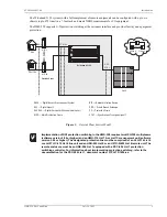
Страница 14: ...by accepting any industry compliant 3192 line card ADC recommends that third party line cards be certified for compliance with a Wideband 3190 Figure 1 shows a functional diagram of a Wideband 3190 sy...

Страница 15: ...version 1 04 or higher and an HMU 319 List 7A or List 7C management unit software version 3 06 or higher The designated protection line must be comprised of an HLU 316 List 6 or an H2TU C 319 List 6...

Страница 16: ...considerations that need to be addressed and mutually agreed upon before proceeding with installation Assignment of personnel Installation tools and methods Protection requirements for personnel equi...

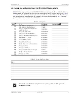
Страница 17: ...tem Part Number Installer Initial H HMS 358 List 5 split power or HMS 358 List 6 redundant power 1156286 or 1156287 H One 1 LIU Module A line interface unit for DS3 or STS 1 150 2232 01 H Two 2 mounti...

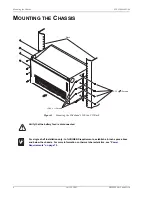
Страница 18: ...hat the battery feed is disconnected For single shelf installation only to fulfill NEBS requirements establish a 4 inch space above and below the chassis For more information on thermal characteristic...

Страница 19: ...he installation kit Apply the amount of torque specified by local codes H 2 Align the chassis mounting bracket holes with the rack s vertical mounting holes The rack s mounting holes should be spaced...

Страница 20: ...amphenol backplane connector Cable ties are included in each kit to secure the cables to the backplane The following procedure should be repeated for each amphenol connector Figure 4 Installing the D...

Страница 21: ...TS Figure 5 shows a standard 16 16 or 25 7 connector cable available in 50 foot or 200 foot lengths See Table 3 and Table 4 on page 10 for pinout descriptions of these two cable connectors Figure 5 50...

Страница 22: ...29 Black Green Brown Black 30 30 62 30 Black Brown Slate Black 31 31 63 31 Black Slate Blue Yellow 32 32 64 32 Yellow Blue Table 4 Cable Connector Pinout and Color Code 25 7 Cable Ring Pins Tip Pins...

Страница 23: ...onfiguration Select the tabbed section that applies to your configuration and only follow those procedures DS3 or STS 1 to DSL configuration see Installing Interface Cables DS3 or STS 1 to DSL on page...

Страница 24: ...H 4 Connect a DS3 coaxial cable to Module A DS3 OUT connector H 5 Proceed to Wiring the Common Access Panel on page 15 H Installer Signature Date OUT DS3 DS3 INPUT POWER 48V 30A MAX 10BaseT 33 1 MALE...

Страница 25: ...e to the field MDF H 3 Connect the 32 pair shielded amphenol female connector to P15 DSX 1 IN LINE CARD and route to the DSX 1 H 4 Connect the 32 pair shielded amphenol female connector to P16 DSX 1 O...

Страница 26: ...llation on page 8 for proper installation of all amphenol connectors H 2 Connect the 32 pair shielded amphenol femaleconnector to P12 HDSL LOOP B and route to the field MDF H 3 Connect the 32 pair shi...

Страница 27: ...lexerin theHMS 358 connectthe shieldedBitsTiming TB4 block Bits A Bits B and the corresponding chassis shield posts to the SONET clock synchronization source H 5 If you have a requirement for an exter...

Страница 28: ...iew Step Procedure Installer Check Whenever installing or removing units from the HMS 358 chassis be sure to wear an antistatic wrist strap and connect it to the ESD strap input 1 Verify that fuses ar...

Страница 29: ...ther end of the ground lug see Figure 11 on page 16 using two 12 24 x 1 2 screws to the CO rack using locally approved methods 6 AWG or larger cables require double screw connectors H 5 Reduce EMI by...

Страница 30: ...ector for slots 1 14 Connect the opposite end of this wire to the 48 Vdc CO battery supply at the fuse panel Fuse is removed If a connector is required conform to local code H 10 Connect a 12 AWG gaug...

Страница 31: ...J34 OS DB 25 RS232 X 25 J30 Female DTE AUX DB 25 RS232 J31 Female H H H H 2 Connect the appropriate network interface cable 10BASE 2 10BASE T or DB 25 from the network to the appropriate network inte...

Страница 32: ...ription 1 TD 2 TD 3 RD 4 NC 5 NC 6 RD 7 NC 8 NC NC no connection Cable must be shielded category 5 Table 7 J30 Pinouts for DB 25 Female Connector OS Interface DTE Pin Description Pin Description 1 NC...

Страница 33: ...ace DTE Pin Description Pin Description 1 NC 14 NC 2 AUX TX 15 NC 3 AUX2 RX 16 NC 4 AUX2 RTS 17 NC 5 AUX2 CTS 18 NC 6 AUX2 DSR 19 NC 7 AUX2 RTN 20 AUX2 DTR 8 NC 21 NC 9 NC 22 NC 10 NC 23 NC 11 NC 24 N...

Страница 34: ...to connect each shelf to the hub Figure 14 Multishelf 10BASE T Configuration Step Procedure Installer Check 1 Connect each CO shelf to an external hub using shielded twisted pair cable Category 5 The...

Страница 35: ...LOOP A GROUP 2 P16 P13 P15 CAUTION VOLTAGES UP TO 200 VDC MAY BE PRESENT UNDER THIS COVER UNDER THIS COVER MAY BE PRESENT VOLTAGES UP TO 200 VDC CAUTION EXT ACO TX RX A NO COM CRT AUD NC COM NO CRT V...

Страница 36: ...f H 3 Connect the other end of the cable to the BNC adapter on the back of the second shelf in the series H 4 Connect each shelf to the next shelf in a series as described in Step 1 through Step 3 H 5...

Страница 37: ...ule H 3 Hold the HMU 319 vertically with the front of the card toward you Align the top and bottom edges of the HMU 319 with the guide rails in the HMU slot and slide the HMU 319 into the rightmost sl...

Страница 38: ...rminal cable to the HMU front panel craft DB 9 port or connect a 25 pin terminal cable to the OS port J30 on any of the shelves in the network If you are connecting the maintenance terminal to the OS...

Страница 39: ...ype public default password and press Procedure 2 1 At the prompt type tao then press 2 After the message Please Log off TL1 session and retype TAO type logoff and then type a semicolon 3 After the Lo...

Страница 40: ...RD slot Alarm Status 1 HLU NORMAL 2 3 HLU NORMAL 4 HLU NORMAL 5 ELU NORMAL 6 ELU NORMAL 7 ELU NORMAL 8 UNK NORMAL 9 HLU NORMAL 10 HLU NORMAL 11 UNK UNKNOWN 12 HLU NORMAL 13 HLU NORMAL 14 HLU NORMAL 15...

Страница 41: ...Technical Assistance Center see Appendix E Product Support on page 84 For more information about passwords refer to the HMU user manual Step Procedure Installer Check The following procedure assumes p...

Страница 42: ...he current time using HH MM 24 hour format and then press H 4 Press to exit the screen and return to the Shelf Status menu H 5 Proceed to Setting the Shelf Identifier Option D on page 30 H Installer S...

Страница 43: ...twork Status menu if in a multishelf configuration or Shelf Status menu if in a single shelf H Installer Signature Date Step Procedure Installer Check 1 From the Shelf Options menu press and then pres...

Страница 44: ...edure of each multiplexer into tabbed sections see Figure 20 Follow the procedures listed only within this tabbed section of the guide Figure 20 Selecting the Proper Tabbed Section for Your Multiplexe...

Страница 45: ...hold down lugs on each side of the chassis front cover The cover folds down H 2 Plug your ESD strap into the ESD input on the front of the chassis H 3 Align the edges of the HXU 358 or HXU 360 multipl...

Страница 46: ...st Inventory Quit Help T1 E1 Ports DS3 Port Password Date and Time Card ID SW Download X Connect Autologout Time Maintenance Port Circuit IDs Restore Defaults ID Card A 10 01 01 10 42 47 ALARMS NONE M...

Страница 47: ...k Status screen type the number of the desired shelf ID 1 through 32 and then press H 2 From the Shelf Status screen press to select Shelf Options H 3 From the Shelf Options screen press to configure...

Страница 48: ...Monitor History Config Test Inventory Quit Help T1 E1 Ports DS3 Port Password Date and Time Card ID Enter Card ID ADC Maintenance Port Circuit IDs Restore Defaults ID Card A 10 01 01 10 42 47 ALARMS N...

Страница 49: ...Menu on page 34 To select the Card ID for the HXU 360 From the Config menu select System Options and then press H 2 Type the system name after Enter Card ID for the HXU 358 or Card ID for the HXU 360...

Страница 50: ...533 or 655 feet Pertains to T1 only not applicable for E1 H Continued Main Monitor History Config Test Inventory Quit Help T1 E1 Ports Port Srvc Mode LBO Code T1 E1 Port Srvc Mode LBO Code T1 E1 1 IN...

Страница 51: ...t the default settings If an HCC 319 List 1 and List 2 cut through card is used these settings should match those of the external line connected to the port 4 Repeat Steps 1 and 3 for each service you...

Страница 52: ...ine Buildout to 100FT default or 450FT H In most applications Transmit Timing should be set to LOCAL 6 Set the BER Threshold to E 03 default E 06 or E 09 This sets the Bit Error Rate BER point at whic...

Страница 53: ...360 10 Exit the Network Status screen by pressing then H 11 If you plan to install a fan assembly proceed to Installing a Fan Assembly Optional on page 51 otherwise proceed to Installing a Line Unit...

Страница 54: ...ol for the backplane Switch 5 OFF activates the HMU craft port for management All other positions should be off ON position is towards the front panel OFF position is towards the card edge connector H...

Страница 55: ...helf Status screen press to select Shelf Options H 3 From the Shelf Options screen press to configure the Mux Type H 4 Press for HXU 359 H 5 Press to exit the screen then press to confirm and save the...

Страница 56: ...STS 1 network connection 2 Type a name for the card network element name and then press The name typed is attached to both cards in a protected system Card A is the multiplexer in slot A Card B is the...

Страница 57: ...ting Up Basic System Parameters Through the Config Menu on page 43 H 2 Press the to select the next value and press to select next field Configure the following options Bits A DS1 speed default or E1...

Страница 58: ...he clock to revert to the primary clock when it is valid Configure the following options Revertive default Non revertive H 5 To manually force the clock synchronization mode set Force to the desired m...

Страница 59: ...not support E1 type service 5 Choose the type of line code B8ZS default or AMI H 6 Choose the line buildout for the DS1 port 131 default 262 393 524 or 655 ft H Continued Main Monitor History Config T...

Страница 60: ...the Virtual Tributary Group VTG 1 through 7 and the Virtual Tributary Slot VTS 1 through 4 Only available combinations are presented for selection H 8 When finished configuring the port reset the port...

Страница 61: ...A when it is selected as a clock synchronization source 3 Select Transport and then press H 4 Type the Tx Path Trace transmit path trace string The string cannot be longer than 40 characters H 5 Set...

Страница 62: ...59 9 Exit the Transport Configuration screen by pressing H 10 If you plan to install a fan assembly proceed to Installing a Fan Assembly Optional on page 51 otherwise proceed to Installing a Line Unit...

Страница 63: ...from the HMS 358 chassis be sure to wear an antistatic wrist strap and connect it to the ESD strap input above the HMU slot on the inside of the chassis 1 Unscrew the two hold down lugs on each side...

Страница 64: ...reen press to select Fan Monitoring H 4 Press to turn on fan monitoring H 5 Press to exit the screen then press to confirm and save the setting H 6 Verify that the fans are running properly and that n...

Страница 65: ...he desired slot then push the unit in until it touches the backplane card edge connector and the retaining latch on the front panel opens Figure 35 H 5 Place your thumbs on the line unit front panel a...

Страница 66: ...Installing Multiplexers LTPH SM 1052 04 54 July 14 2002 HMS 358 List 5 and List 6 Figure 36 Securing the Modules with the Retention Bar Retention bar...

Страница 67: ...efer to the HRU user manual for details User options usually include setting the DS1 receive level TLOS Sealing current Local or line power selection H Refer to the HRU pinout in Figure 37 if remote c...

Страница 68: ...rminal Main menu select from the Main menu to display the line unit System Inventory screen H 3 Press the corresponding letter of the unit of which you want to change the circuit ID H 4 Type a text st...

Страница 69: ...helf Status screen press to select Alarm Management H 3 Type the slot number of the line unit you want to enable H 4 Press an appropriate or response for the alarm setting you are changing H 5 Proceed...

Страница 70: ...n page 60 Placing the Line Unit in Service Using an HXU 358 or HXU 360 Multiplexer Step Procedure Installer Check The following procedure assumes proper TAO login For proper login procedure please ref...

Страница 71: ...When you type a slot number x one of the following prompts appears Do you want to ENABLE alarm settings for Line Unit x Y N Do you want to DISABLE alarm settings for Line Unit x Y N H 3 Press an appro...

Страница 72: ...nstaller Check 1 From the Shelf Options screen press to select Alarm Management The following prompt appears Which Line Unit do you want to change the alarm settings on 1 28 E nable All D isable All H...

Страница 73: ...the DS3 line Activate from the HXU 358 or HXU 360 Test menu TLB1 a b Terminal Loopback to the network at the DSX 1 line Activate from the HXU 358 or HXU 360 Test menu FLB1 a b Facility loopback to the...

Страница 74: ...etention bar at the top of the chassis to allow insertion of the module H 4 Plug the HTC 319 into the shelf slot whose circuit you want to test H 5 Set the four position slide switch S1 on the HTC 319...

Страница 75: ...ap input 1 If you have not already done so open the chassis front cover by unscrewing the two hold down lugs on the upper corners The cover folds down H 2 Be sure to plug your ESD wrist strap into the...

Страница 76: ...ates and reports various status messages 2 Verify that the line unit attempts to communicate with downstream devices status LED flashes red If downstream devices are successfully identified and the lo...

Страница 77: ...nd Minor alarms CR A critical alarm is generated if power to the shelf or one of the A B feeds has been lost causing the Visible and Audible Critical Alarms to be asserted shelf temperature exceeds 17...

Страница 78: ...ritical Major Minor and Far End alarms to the HMU CRITICAL The HXU reports a critical alarm if it detects a critical service affecting fault more than four faulty DS1 inputs or DS2 failure MAJOR A maj...

Страница 79: ...e conditions exist on a line unit the line unit status indicates NORMAL For this reason use of the line unit Errored Seconds Threshold alarm option is not recommended Refer to the line unit documentat...

Страница 80: ...adapter has a unique hardware address assigned by the manufacturer and coded into the circuitry On a local network each piece of equipment picks up data which is addressed to it In order for one devic...

Страница 81: ...LAN and separated from any external network by a router If this is not the case then consult your system administrator Table 12 provides some suggestions for addressing your system if it is on its own...

Страница 82: ...instructions Figure 41 Common Access Panel Specification All relay contacts are rated at 48 Vdc at 1A Table 13 Relay Specifications Parameter Rated Load 0 5A at 125 Vac Maximum switching capacity 62 5...

Страница 83: ...hers HMUs HMU 319 List 7A HMU 319 List 9 Operational Altitude 197 ft 60m below sea level to 13 000 ft 3962m above sea level Relative Humidity Operational 5 to 85 non condensing Short term 5 to 90 Non...

Страница 84: ...e power fed to the remote locations Power dissipation is that part of the total power that is consumed by the CO end of the system It represents the CO heating and is useful in calculating the power d...

Страница 85: ...ernal fuse tray typically mounted at the top of the CO rack The HMU reports all fuse alarms within the HMS 358 Each chassis within the rack must be equipped with A and B fuses for proper power protect...

Страница 86: ...se Rating at 150 Overcurrent 5 10 No Multiplexers 2 Multiplexers No Multiplexers 2 Multiplexers No Doublers Max Doublers No Doublers Max Doublers No Doublers Max Doublers No Doublers Max Doublers HLU...

Страница 87: ...om a factor Figure 43 Bay Heating Based on Doublers per Chassis FANS For a 0 C to 50 C 32 F to 122 F operating environment a fan assembly is required for any of these situations One system with 230W p...

Страница 88: ...mands The HMU expects a complete TL1 command that is terminated by a semicolon The Ethernet Port J34 on the rear of the Wideband 3190 may also be used for NMA mode as an alternative to the X 25 OS por...

Страница 89: ...ct press to reset the system The OS port is now configured for X 25 X 25 Configuration Using TL1 Commands The following steps describe how to configure the OS port for X 25 using TL1 commands 1 Connec...

Страница 90: ...lowing default settings see Table 16 below for a description of the line indicators A B Channel One 2 way Minimum LCI 1 B B Channel One 2 way Maximum LCI 20 C Maximum Number of PVC Supported 2 D PVC0...

Страница 91: ...rt is not configured by the user but is determined by the TCP port opened by the client application The following table shows the TCP port number and the operating mode The HMU cannot operate both 10B...

Страница 92: ...ield and can be made through P11 TX and P12 RX or through wire wrap connections under the field access cover Figure 44 Group 2 Port 2 connections can be accessed through four wire wrap posts under the...

Страница 93: ...Figure 44 on page 80 loosen the 4 40 PH screw slide the cover to the right and lift it away from the chassis H 2 Perform the required wire wrapping procedures determined by CO management Figure 45 sh...

Страница 94: ...of the same type required for line protection H STS 1 multiplexer HXU 359L2V11 H DS3 multiplexer HXU 358 V104 H DS3 multiplexer HXU 360 L1 Line Units H HDSL line units for 3190 mechanics HLU 319 List...

Страница 95: ...System Interface User System Language Bellcore Craft interface and is compatible with TL1 TR TSY 000827 Issue 1 November 1988 OTGR Generic Operations Interface Non OSI Communications Architecture Bell...

Страница 96: ...stem Turn Up and Testing Network Monitoring upstream or downstream Power Monitoring and Remote Surveillance Service Maintenance Agreements Systems Operation ADC Technical Assistance Center 800 638 003...

Страница 97: ...l Signal Cross connect Level 1 DTE Data Terminal Equipment E EMI ElectroMagnetic Interference ESD Electrostatic Discharge F FGND Frame Ground FLB Facility Loopback H HDSL High bit rate Digital Subscri...

Страница 98: ...inal Loopback S S1 Slide Switch SELV Safety Extra Low Voltage SID Shelf Identifier SSC2 Special Signaling Channel 2 STS 1 Synchronous Transport Signal 1 SVC Switched Virtual Circuit T TAO Terminal Acc...

Страница 99: ...ist 6 July 14 2002 87 PROJECT MEMBER SIGNATURES Complete the following table by printing the title and name of each project member followed by their signature This list may then be removed and stored...

Страница 100: ...n page 5 Check if not applicable H Verified Presence of Proper Tools and Supplies see Before You Begin on page 4 Check if not applicable H Reviewed Safety Precautions see Safety Warnings and Notices o...

Страница 101: ...H Connected to Network Interface see Connecting the Network Interface on page 19 Check if not applicable H Installed Management Unit see Installing Multiplexers on page 32 Check if not applicable H In...

Страница 102: ...s see Installing a Remote Unit HRU on page 55 Check if not applicable H Set Up Circuit ID s see Setting Up Circuit IDs on page 56 Check if not applicable H Placed Line s In Service see Placing the Li...

Страница 103: ...Compatibility 91 Compliance 92 Components system 5 Connectors cable pinouts 11 12 P10 9 P11 14 15 16 P12 14 15 16 P13 16 P14 16 P15 15 P16 15 P9 9 Craft port 29 48 Cross connect 69 Cut through Card 6...

Страница 104: ...42 HXU 359 configuring DS1 services 53 configuring STS 1 transport 55 enabling alarms 68 entering card ID 50 installation 48 setting up basic system parameters 49 setting up system clock synchronizati...

Страница 105: ...80 Power Access connector 20 Power cable 18 Power requirements 80 81 Power sources 82 R Returns 93 Routers 78 S Safety warnings and notices iv SELV iv Shelf Identifier 33 Wideband 3190 functional dia...

Страница 106: ...Index LTPH SM 1052 04 94 July 14 2002 HMS 358 List 5 and List 6 V Verification 73 W Wirewrapping non multiplexer applications 89 Wiring fuse panel 20 X X 25 network 27...

Страница 107: ...stored will be free from material defects under normal use ADC will replace defective media at no charge if it is returned to ADC during the 30 day warranty period along with proof of the date of shi...

Страница 108: ...D FIRM ISO 9001 TL 9000 ADC DSL Systems Inc 14402 Franklin Avenue Tustin CA 92780 7013 Tel 714 832 9922 Fax 714 832 9924 Technical Assistance Tel 800 638 0031 Tel 952 917 3222 Fax 714 730 2400 DOCUMEN...

Отзывы: