background image

Loopback Operation


 150-319-205-05, Issue 5

42

January 26, 2000

 ELU-319 List 5E and List 6E

L

OOPBACK

 O

PERATION

I

NITIATING

 M

ANUAL

 L

OOPBACK

 S

ESSIONS

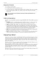
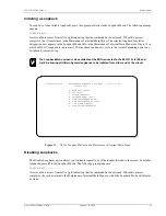
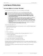
A manual loopback session allows you to select one of four HiGain system loopbacks. 

To initiate a manual loopback session:

1

Press both the MODE and SEL buttons on the front panel for at least 3 seconds. The following message 
appears on the front panel display:

MAN LPBK

followed by the message:

NLO?

2

Do one of the following:

To execute an E1 loopback, press the SEL button. The message changes from 

NLO

? to 

NLOC

.

To execute an NREM loopback:

Press the MODE button. The message changes from 

NLO? 

to 

NRE

?

Press the SEL button to execute the NREM loopback.

3

To execute a CRE loopback, press the MODE button again.

4

To execute a CLO loopback, press the MODE button a third time.

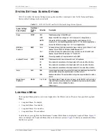
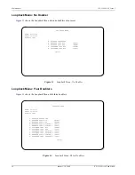
These same loopbacks can be initiated from the RS-232 craft port by choosing the Loopback Mode, option D, 
from the Main Menu. This displays the Loopback Menu (

Figure 13 on page 30

) from which any of the loopbacks 

can be initiated or terminated.

All loopbacks can be initiated by a command from HiGain itself (front panel buttons or maintenance 
screen selections).

Any of the HiGain loopbacks can be executed using the MODE and SEL buttons. 

In general, to execute a manual loopback session using the MODE and SEL buttons:

The next loopback option can be presented by pressing the MODE button, but the 
previously executed loopback remains active until the SEL button is pressed and a 
different loopback is activated. 

If neither button is pressed for a period of 30 seconds, and no loopback is in effect, the 
manual loopback session terminates and the normal margin displays reappear. 

If any loopback is in effect, the 30-second timeout is inhibited. The active loopback and 
the manual loopback session continue until the loopback times out in accordance with the 
LBTO setting. 

Pressing both buttons for 3 seconds terminates any active loopback, ends the Manual 
loopback session and returns the display to normal mode. 

Содержание 150-1236-55

Страница 1: ...HiGain HiGain USER MANUAL ELU 319 List 5E and List 6E Line Unit Product Catalog 150 1236 55 and 150 1236 65...

Страница 2: ...Disclaimer of Liability Information contained in this document is company private to ADC DSL Systems Inc and shall not be modified used copied reproduced or disclosed in whole or in part without the w...

Страница 3: ...pect the contents for signs of damage If the equipment has been damaged in transit immediately report the extent of damage to the transportation company and to ADC DSL Systems Inc Order replacement eq...

Страница 4: ...Inspecting Shipment 150 319 205 05 Issue 5 iv January 26 2000 ELU 319 List 5E and List 6E...

Страница 5: ...ontrol Bus 10 Fuse Alarm 10 System Alarm Output Pin 11 Functional Description________________________________________________________________ 12 Timing 12 Power Consumption without Doublers 13 Maximum...

Страница 6: ...History Screen Without Doubler 35 The 7 Day History Screen With Doubler 36 View Alarm History 37 Alarm History Screen Without Doubler 38 Alarm History Screen With Doubler 39 System Inventory Screen 40...

Страница 7: ...1 8 Span Status Screen No Doubler 22 9 Span 1 Status Screen 23 10 Span 2 Status Screen 23 11 Set Clock Screen 26 12 System Settings Screen 27 13 Loopback Menu No Doubler 30 14 Loopback Menu Three Doub...

Страница 8: ...st 6E 13 8 EDU 451 List 1 or List 2 Maximum Power Parameters No Doubler 14 9 EDU 409 List 2 Maximum Power Parameters Two Doublers 14 10 EDU 409 List 2 Maximum Power Parameters Three Doublers 14 11 Nav...

Страница 9: ...h three doublers 14 6 km 0 51 mm 24 AWG Four line powered spans three doublers and a remote Low line power option 140 V for circuits with a single doubler Reduced power consumption Ultra low wander St...

Страница 10: ...h cable gauge change The E1 operating ranges on unimpaired cable pairs are shown in Table 2 as a function of cable gauge and average margin In general HiGain systems Operate with any number of other E...

Страница 11: ...e to three doublers may be used in the HDSL loops between the ELU and ERU The ELU 319 List 5E and List 6E can power three doublers and a remote unit ERU 412 List 1E and List 2E for a total of four spa...

Страница 12: ...sure Charles Ind 3192 28 slot connectorized Charles Ind 3192 9F Alarm Card Larus 1185 28 slot connectorized Larus 1184 Alarm Card Charles Ind 3192 WR 28 slot wire wrap Charles Ind 343 00 12 to 14 slot...

Страница 13: ...doublers allowed for a given circuit depending upon the doubler and line unit models used to implement the circuit Any restrictions on the ERU models All spans are fully HCDS compliant unless otherwis...

Страница 14: ...t port Warranty Control number Card edge connector FRONT PANEL The ELU 319 List 5E front panel is shown is Figure 1 The front panel components are described in Table 4 on page 7 Figure 1 ELU 319 List...

Страница 15: ...ccess to XMT and from RCV the HDSL span at the DSX 1 interface Allows the two E1 payloads to be monitored Craft RS 232 port Provides bidirectional communication between the unit and an external termin...

Страница 16: ...ers of the first doubler and either the ERU or second doubler are trying to establish contact with each other on Loops 1 or 2 of Span 2 S3L1 or 2 Signal 3 Loop 1 or Loop 2 The transceivers of the seco...

Страница 17: ...r Down code see Table 1 on page 2 and Table 9 on page 14 PWR FEED GND Power Feed Ground One of the HDSL loops has been grounded BER Bit Error Rate A system BER alarm is in effect BAD RT No response fr...

Страница 18: ...e displays periodically on the ELU 319 List 5E and List 6E front panel display Fuse Alarm Pin 10 on the card edge connector is a Fuse Alarm that is driven to 48 V whenever its onboard fuse opens It em...

Страница 19: ...Card in position 29 of the High Density HD shelf The ELU 319 forces Pin H to 5 V maximum of 10 mA for a system alarm condition Pin H then remains at 5 V for the duration of the alarm condition If the...

Страница 20: ...U 319 is shown in Figure 3 The ELU 319 receives a 2 048 Mbps G 703 data stream from the G 703 digital cross connect interface The ELU 319 contains a G 703 frame synchronizer controlled by an 8 bit mic...

Страница 21: ...enclosures are determined by applying its power parameters to the manufacturer s requirements for each specific housing The 48 V Power Consumption is the maximum total power that the ELU 319 List 5E...

Страница 22: ...ops Table 10 applies to three doubler line powered circuits on 9 kft 26 AWG 0 4 mm loops Table 8 EDU 451 List 1 or List 2 Maximum Power Parameters No Doubler ERU Model 48 V Power Consumption W Heat Di...

Страница 23: ...d guides for the desired slot then push the unit back until it touches the backplane card edge connector see Figure 4 Figure 4 Installing the ELU 319 List 5E and List 6E into a Shelf 2 Place your thum...

Страница 24: ...current displayed mode to the selected setting and then advances to the next configurable parameter After the last parameter has been selected a Confirm Yes No message appears on the front panel disp...

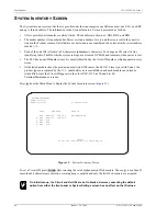
Страница 25: ...2000 17 Displaying System Inventory To scroll through an inventory of system parameters press the MODE button for 4 or more seconds The following parameters are displayed ELU software version number E...

Страница 26: ...erminal 1 Connect a standard 9 pin terminal cable to the RS 232 craft port on the ELU 319 List 5E and List 6E front panel 2 Connect the other end of the console cable to the console port on the mainte...

Страница 27: ...llowing message and identifies the name of a field where the invalid entry occurred error This happens only for margin alarm threshold Otherwise there is no response to an invalid entry ACCESSING THE...

Страница 28: ...options 27 Loopback Menu Provides access to subscreens that allow you to issue and disable loopbacks from both the network and customer side 29 View Performance Data Provides access to subscreens that...

Страница 29: ...tatus Performance Data and Performance History may display as many as five screens to depict an ELU 319 List 5E and List 6E system Figure 7 System HDSL Spans From each Span Status screen you can Press...

Страница 30: ...onfiguration some information will change in Figure 8 Figure 9 and Figure 10 on page 23 A SPAN STATUS TIME 00 14 11 DATE 01 24 00 Circuit ID ALARMS NONE LOOPBACK OFF POWER LEVEL LOW ELU ERU HDSL 1 HDS...

Страница 31: ...NE LOOPBACK OFF POWER LEVEL HIGH ELU EDU1 HDSL 1 HDSL 2 HDSL 1 HDSL 2 cur min max cur min max cur min max cur min max MARGIN 21 21 21 21 21 21 21 21 21 21 21 21 dB PULSE ATTN 19 19 20 19 dB INS LOSS 2...

Страница 32: ...d to the 260 kHz loss of the cable pair The pulse attenuation is a more direct indication of the loop attenuation to the 2B1Q signal than is the 260 kHz loss The normal HiGain ATTN operation range is...

Страница 33: ...1 Network Doubler 1 Loopback Loopback at Doubler 1 to network initiated by IOR code or by Manual Loopback buttons on the ELU 319 List 5E front panel or by the maintenance terminal NDU2 Network Doubler...

Страница 34: ...e Update Remote field displays Update the ERU Time and Date The remote unit date and time is set by using this option To update the remote do one of the following Press to update the ERU to the same d...

Страница 35: ...bines the one second TEC counts in both directions for the last 60 seconds It uses this 1 minute Total System Error Count TSEC to generate an alarm if it exceeds the selected BER threshold of 1E 6 or...

Страница 36: ...non doubler applications and 112 V for doubler applications HIGH forces the HDSL line voltage to its high 112 V level for applications It is needed to allow the ELU to power circuits that are providin...

Страница 37: ...for non doubler applications and 112 V for doubler applications HIGH Forces the HDSL line voltage to 112 V for all applications BER Alarm Threshold BERT 1E 6 Activates closes the SmartJack alarm relay...

Страница 38: ...ACK MENU TIME 00 15 34 DATE 01 24 00 CIRCUIT ID A DISABLE LOOPBACKS B NETWORK LOOP ELU NLOC C NETWORK LOOP ERU NREM G CUSTOMER LOOP ELU CREM H CUSTOMER LOOP ERU CLOC E xit LOOPBACK MENU TIME 00 03 33...

Страница 39: ...ck Mode in the Maintenance Terminal Main Menu Disabling Loopbacks The Disable Loopbacks option allows you to disable cancel any of the loopbacks listed in the screen To disable loopbacks press in the...

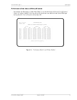
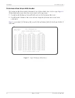
Страница 40: ...in Table 16 From each Performance Data screen you can do the following Press to view the previous 4 hour data screen Press to view the next 4 hour data screen Press to exit Press to view the next avai...

Страница 41: ...S UNAVAILABLE SECONDS G 703 HDSL 1 HDSL 2 ELU ERU ELU ERU ELU ERU 20 30 000 000 000 000 000 000 000 000 000 000 000 000 20 45 000 000 000 000 000 000 000 000 000 000 000 000 21 00 000 000 000 000 000...

Страница 42: ...CONDS G 703 HDSL 1 HDSL 2 ELU ERU EDU3 ERU EDU3 ERU 00 00 000 000 000 000 000 000 000 000 000 000 000 000 00 15 000 000 000 000 000 000 000 000 000 000 000 000 00 30 000 000 000 000 000 000 000 000 00...

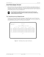
Страница 43: ...7 Day History Screen for Span 1 No Doubler Since the ELU 319 is considered the master module this clears all performance data screens at both the ELU 319 and the ERU The RS 232 terminal interface at...

Страница 44: ...to the ERU Figure 19 7 Day History Screen Span 4 F S Time 03 09 34 7 DAY HISTORY CIRCUIT ID SPAN 4 ERRORED SECONDS UNAVAILABLE SECONDS G 703 HDSL 1 HDSL 2 ELU ERU EDU3 ERU EDU3 ERU 01 05 00000 00000 0...

Страница 45: ...ications as well Table 17 Alarm History Fields and Descriptions Field Description Type Identifies the type of alarm LOS G 703 ELU First and last instance of LOS at the ELU Current condition number of...

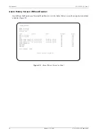
Страница 46: ...re 20 Figure 20 Alarm History Screen for Span 1 G ALARM HISTORY TIME 00 04 06 DATE 01 24 00 CIRCUIT ID Type First Last Current Count LOS G 703 ELU OK 000 LOS G 703 ERU OK 000 BER OK 000 SPAN1 LOSW HDS...

Страница 47: ...to advance through the alarm history screens for the various spans Figure 21 is an example of an Alarm History screen that lists history for the fourth span Doubler 3 to the ERU Figure 21 Alarm Histo...

Страница 48: ...ified by the Circuit ID number which appears in every screen All detected modules have the product number listed Whenever the ELU 319 loses sync with Span 1 the product types are replaced by the N A l...

Страница 49: ...ose sync word LOSW a system alarm condition exists However since the ELU 319 enters a self test cycling mode the front panel LED lights yellow instead of red and the SELF TEST message is displayed ins...

Страница 50: ...option D from the Main Menu This displays the Loopback Menu Figure 13 on page 30 from which any of the loopbacks can be initiated or terminated All loopbacks can be initiated by a command from HiGain...

Страница 51: ...niature 210 series bridging jacks as shown in Figure 1 on page 6 Connecting one cable between the two bridging jacks and another between the two SPAN jacks splits the XMT and RCV and creates metallic...

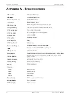
Страница 52: ...2 048 Mbps 200 bps G 703 Line Format HDB3 G 703 Frame Format Unframed only Maximum Heat Dissipation 5 W without doubler 7 W with doubler typical Fusing Internal connected to FUSE ALARM output on pin...

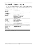
Страница 53: ...ntegration Testing System Turn Up and Testing Network Monitoring upstream or downstream Power Monitoring and Remote Surveillance Service Maintenance Agreements Systems Operation ADC Technical Assistan...

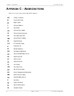
Страница 54: ...Cyclic Redundancy Check CREM Customer Remote Loopback DDS Digital Data Service G 703 E1 Transmission System ES Errored Seconds ESF Extended Superframe HCDS High Capacity Digital Service HDSL High bit...

Страница 55: ...riod is at ADC s option either a return of the price paid or b repair or replace of the software ADC also warrants that for a period of thirty 30 days from the date of purchase the media on which soft...

Страница 56: ...Avenue Tustin CA 92780 7013 Tel 714 832 9922 Fax 714 832 9924 Technical Assistance Tel 800 638 0031 Tel 714 730 3222 Fax 714 730 2400 DNV Certification Inc REGISTERED FIRM ISO 9001 TL 9000 DOCUMENT 15...

Отзывы: