


150-454-111-06
Appendix B - Technical Reference
HRE-454
February 25, 2000
27
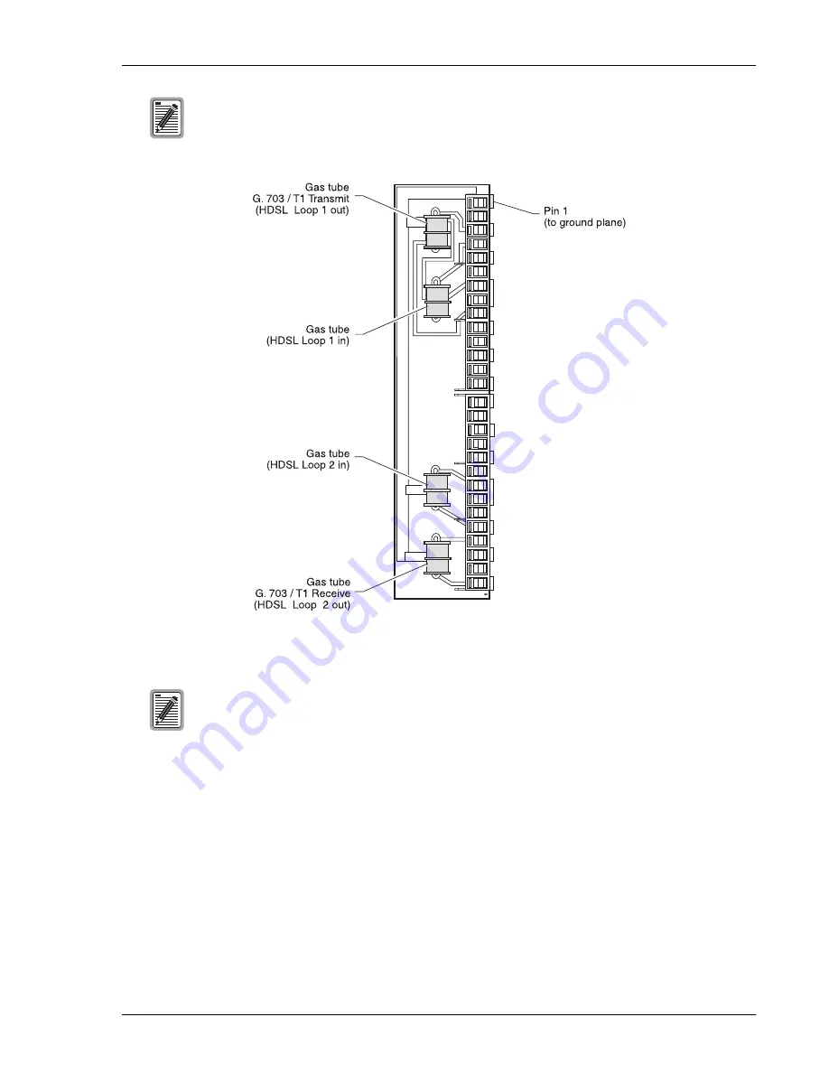
Figure 13.
Lightning Protection Unit (LPU)
Cable Stub and Pressurization
Every HRE-454 is equipped with a single-screened cable stub. Refer to
for a complete
description of the cable stub. The stub is available as a gel- or air-filled unit. It is secured to the enclosure plate by
a cable strain relief adapter. The cable stub is spliced out and encapsulated in the polyurethane that is poured into
the enclosure base. This provides an airtight seal at the cable entry point.
The pressurized enclosure has an air inlet tube that accompanies the air-filled stub. The tube connects the inside
of the enclosure to the main feeder cable which enables dry air or dry nitrogen to flow from the main cable to the
cable stub through the air cutoff valve. The air cutoff valve controls the dry air or nitrogen flow through the air
inlet tube as described in
“Air-filled Stub Units” on page 5
Although the individual gas tubes are field replaceable components, ADC recommends
replacing the entire LPU when any of its protector tubes are suspect. See
for details on replacing an LPU.
The gas tube parameters are equivalent to a TTI 47 BT. The Vdc breakdown ranges from 300 to
500 volts. The tube can withstand at least 400, 10/1000, or 500 amp discharges. (Amp discharges
are quantities of discharges that occur before system degradation.)
Содержание 150-1122-03
Страница 4: ...Inspecting Shipment 150 454 111 06 iv February 25 2000 HRE 454 ...
Страница 45: ...150 454 111 06 Appendix B Technical Reference HRE 454 February 25 2000 37 Figure 18 HRU 512 Pin Assignments ...
Страница 46: ...Appendix B Technical Reference 150 454 111 06 38 February 25 2000 HRE 454 Figure 19 HRU 612 Pin Assignments ...
Страница 49: ...150 454 111 06 Appendix B Technical Reference HRE 454 February 25 2000 41 Figure 22 HRU 402 Pin Assignments ...
Страница 50: ...Appendix B Technical Reference 150 454 111 06 42 February 25 2000 HRE 454 Figure 23 H2TU R 402 Pin Assignments ...
Страница 51: ...150 454 111 06 Appendix B Technical Reference HRE 454 February 25 2000 43 Figure 24 HRE 454 Wiring Interfaces ...
Страница 74: ...Appendix D Glossary 150 454 111 06 66 February 25 2000 HRE 454 ...


