U
SER
M
ANUAL
HRE 425
H0333-A
HRE-425 List 1 Remote EnclosureProduct Catalog: 150-1114-01CLEI: T1MFF504
Страница 1: ...USER MANUAL HRE 425 H0333 A HRE 425 List 1 Remote Enclosure Product Catalog 150 1114 01 CLEI T1MFF504...
Страница 2: ...in this document is company private to ADC DSL Systems Inc and shall not be modified used copied reproduced or disclosed in whole or in part without the written consent of ADC Contents herein are curr...
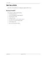
Страница 3: ...for signs of damage If the equipment has been damaged in transit immediately report the extent of damage to the transportation company and to ADC DSL Systems Inc Order replacement equipment if necessa...
Страница 4: ...150 425 100 04 iv September 22 1999 HRE 425 List 1...
Страница 5: ...lane 6 Power and Grounding 6 Fuse Alarm 7 Slot pin Assignments 9 Field Side HDSL Connections 11 CPE DS1 G 703 Connections 13 Turn Up 15 Specifications__________________________________________________...
Страница 6: ...elf Fusing Backplane Wiring and Bus Connections 8 7 HDU 451 and EDU 451 Pin Assignments 9 8 HLU 431 Pin Assignments 10 9 ERU 412 Pin Assignments 11 10 DS1 G 703 RJ48C Harmonic Cable Interface Assembly...
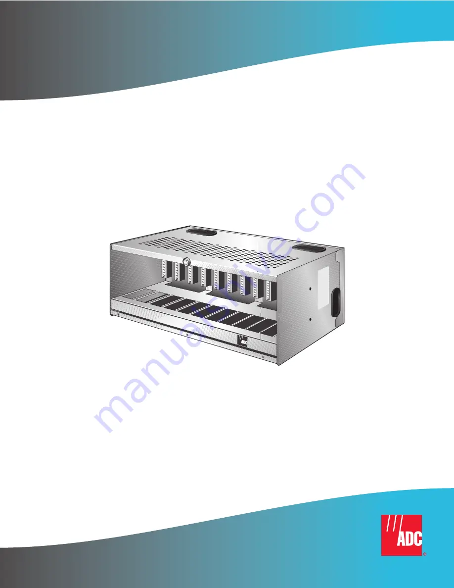
Страница 7: ...the top or bottom panels A variety of grommited cable access openings are located on the enclosure s top bottom sides and rear covers FEATURES The HRE 425 List 1 provides the following features 12 sl...
Страница 8: ...application of the HRE 425 List 1 Remote Enclosure is to house the remote units of a HiGain repeaterless T1 transmission system Because the HRE 425 uses standard 400 mechanics slots it can accommodat...
Страница 9: ...STALLATION KIT The installation kit contains the following items four rack mounting screws four bracket attaching screws with locking nuts four plastic cable tie wraps one spare 0 5A fuse one 2A fuse...
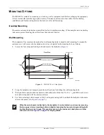
Страница 10: ...he four rear panel locking bolts and remove the backplate Figure 2 Figure 2 HRE 425 List 1 Backplate 2 Using the backplate as a template mark the wall locations for drilling the wall mounting holes 3...
Страница 11: ...t with the rack size 19 or 23 inch 2 Attach the rack mounting brackets to the bracket mounting holes see Figure 3 on each side panel with the four bracket attaching screws and locking nuts 3 Attach th...
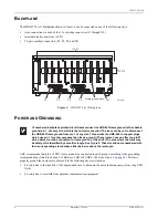
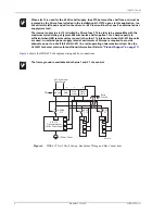
Страница 12: ...ability of the ungrounded case to attenuate the noise inducing energy from stray EMI fields bit errors due to crosstalk from adjacent communication equipment 12 numbered backplane printed circuit trac...
Страница 13: ...ground the case to avoid shock hazard Damage to the HRU circuits may result if the discharge path to earth ground for its secondary surge voltage protection components is missing Connect pin 4 of TB1...
Страница 14: ...compatible with the maximum current rating of typical 400 mechanics shelf supplies This 2 Amp capacity is sufficient when HRU remote units are used in the other 11 slots but not when HLU 431 line unit...
Страница 15: ...gures Figure 7 shows the slot pin assignments for the HDU 451 and EDU 451 Figure 7 HDU 451 and EDU 451 Pin Assignments 27 25 23 21 19 17 15 13 11 9 7 3 5 1 HDSLL2OUTTIP HDSLL2OUTRWG DS1TIP1 DS1RING1 H...
Страница 16: ...13 11 9 7 3 5 1 DS1TIP DS1RING HDSL2RING1 HDSL2TIP1 RS 232DATAOUT ALARM MANAGEMENT 48V FUSEALARM CIRCUITGND FACTORYBURN IN DONOTUSE DS1RING1 HDSL1RING XMT RCV HDSL1TIP DS1TIP1 CHASSISGROUND 28 26 24 2...
Страница 17: ...requires BNC connectors that are not available in the HRE 425 The HDSL 1 designation refers to Loop 1 and HDSL 2 to Loop 2 If these leads are reversed a CHREV message is displayed in the ALARMS displa...
Страница 18: ...re used Table 1 HDSL Connectors P3 Doubler Loop 1 In HDSL Loop 1 In a a P3 Pins 13 through 25 and 38 through 50 are unused Slot Pin No P3 Pin No Card Slot P3 Pin No Slot Pin No 1 1 26 2 2 27 13 3 3 28...
Страница 19: ...Table 2 Table 2 DS1 G 703 Doubler HDSL Connectors P1 DS1 G 703 Doubler HDSL Loop 2 Out a a P1Pins 13 through 25 and 38 through 50 are unused Slot Pin No P1 Pin No Card Slot P1 Pin No Slot Pin No 1 1 2...
Страница 20: ...to the top bottom or either of the two side plates through the wall mounting holes located on all 4 of these plates Figure 3 on page 5 shows the locations of these mounting holes on the side panel Si...
Страница 21: ...e 1 on page 1 then gently lower the panel 2 Insert the card in the assigned slots Refer to the card s technical practice for the appropriate turn up procedure Before handling the plug in modules attac...
Страница 22: ...8 Connector Option Cables 12 port RJ48 C harmonic connector cable assembly 150 2201 01 12 port RJ48 X harmonic connector cable assembly 150 2201 02 In shelf Power Supply Option 120 Vac to 48 Vdc 2 A W...
Страница 23: ...toring upstream or downstream Power Monitoring and Remote Surveillance Service Maintenance Agreements Systems Operation ADC Technical Assistance Center 800 638 0031 714 730 3222 Fax 714 730 2400 Email...
Страница 24: ...umber Label Locations Table 3 HRE 425 List 1 Bar Code and Configuration Number Label Descriptions Item Description CLEI ECI Bar code label Contains human readable Common Language Equipment Identifier...
Страница 25: ...r Premises Equipment DS1 Digital Signal level 1 ECI Equipment Catalog Item HCDS High Capacity Digital Service HDSL High bit rate Digital Subscriber Line HDU HiGain Doubler Unit HLU HiGain Line Unit HR...
Страница 26: ...150 425 100 04 20 September 22 1999 HRE 425 List 1...
Страница 27: ...ges ADC may use reconditioned parts for such repair or replacement This warranty does not apply to any product which has been repaired worked upon or altered by persons not authorized by ADC or in ADC...
Страница 28: ...DSL Systems Inc 14402 Franklin Avenue Tustin CA 92780 7013 Tel 714 832 9922 Fax 714 832 9924 Technical Assistance Tel 800 638 0031 Tel 714 730 3222 Fax 714 730 2400 DOCUMENT 150 425 100 04 Of 5 12477...