background image

Installation and Commissioning Guide - Wall Hung Split System

Doc. No.9590-5007  

Ver. 2  210416

Installation and Commissioning Guide

Wall Hung Split System


40

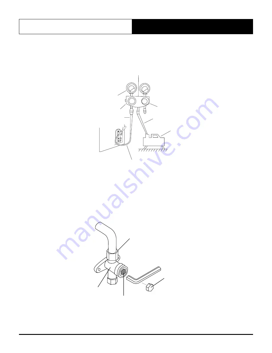
12.02.  Evacuation Instructions

Before using the manifold gauge and vacuum pump, read their operation manuals to familiarize yourself with how to 
use them properly.

Manifold Gauge

Compound gauge

-76cmHg

Low pressure valve

High pressure 

valve

Pressure hose / 

Charge hose

Charge hose

Vacuum

pump

Pressure gauge

Low pressure valve

Vacuum Pump

Charge Hose

High Pressure Valve

Low Pressure Valve

Pressure Gauge

Compound Gauge

-76 cmHg

                 Low Pressure Valve


Pressure Hose/

Charge Hose

Manifold Gauge

1.  Connect the charge hose of the manifold gauge to service port on the outdoor unit’s low pressure valve.
2.  Connect another charge hose from the manifold gauge to the vacuum pump.
3.  Open the Low Pressure side of the manifold gauge. Keep the High Pressure side closed.
4.  Turn on the vacuum pump to evacuate the system.
5.  Run the vacuum until the compound meter reads 500 microns.
6.  Close the Low Pressure side of the manifold gauge, and turn off the vacuum pump.
7.  Wait for 5 minutes, then check that there has been no change in system pressure.

Flare nut

Cap

Valve body

Valve stem

Flare Nut

Valve Body

Valve Stem

Cap

Содержание WRC-026CS

Страница 1: ...ning Guide Model Numbers WRC 026CS WRC 035CS WRC 050CS WRC 072CS WRC 085CS WRE 026CS WRE 035CS WRE 050CS WRE 072CS WRE 085CS IMPORTANT NOTE Please read this manual carefully before installing or operating your air conditioning unit That s better That s Actron ...

Страница 2: ...12 09 Outdoor Unit Installation 22 10 Refrigeration Piping Connection 27 11 Wiring 30 11 01 Outdoor Unit Wiring 32 11 02 Indoor Unit Wiring 33 11 03 Indoor Unit Wiring Diagram 35 11 04 Outdoor Unit Wiring Diagram WRC 026CS WRC 035CS 36 11 05 Outdoor Unit Wiring Diagram WRC 050CS WRC 072CS WRC 085CS 37 11 06 Electrical Connection 38 12 Leak Test and Air Evacuation 39 12 01 Leak Test 39 12 02 Evacua...

Страница 3: ...st the right amount of cooling or heating capacity you demand Even in extreme conditions the unit will still supply the required demand at peak performance Energy Efficient Refrigeration Circuits The ActronAir system is designed with a split ducted refrigeration circuit that delivers only the amount of cooling or heating actually required to maintain your desired comfort at the most optimum effici...

Страница 4: ...uel dependency and high network grid demand 03 Safety Instructions Only licensed HVAC technicians should install and service this air conditioning equipment Improper service or alteration by an unqualified technician could result in significant and major damage to the product or property which may render your warranty null and void Such unqualified service could also lead to severe physical injury...

Страница 5: ...nd have come to a complete stand still before servicing the equipment Beware of pinch point and sharp edges which can cause cutting injury Secure the fans against accidental contact Always wear appropriate PPE and remove any dangling jewellery and protect long hair by wearing a cap Ensure that no loose clothing can be caught entangled in moving parts VISUAL INSPECTION AND WORK ASSESSMENT Work area...

Страница 6: ...pport the unit and accessories weight Install anti vibration rubber installer to supply under all of the unit s feet to help reduce noise and minimize vibration transfer through the foundation Ensure that all anti vibration rubbers are rated to provide stable support without impairing the unit s structural integrity Diameter or width of anti vibration rubber s must be at least equal to the width o...

Страница 7: ...es to install the air conditioner Improper installation may result in water leakage electrical shock fire or cause the equipment to fail Name Shape Quantity Mounting plate 1 Clip anchor 5 Mounting plate fixing screw ST3 9 X 25 5 Remote controller Humidity Boost 1 Fixing screw for remote controller holder ST2 9 x 10 2 Dry battery AAA LR03 2 Seal 1 Drain joint 1 Remote control holder 1 Owner s manua...

Страница 8: ...Wall Hung Split System 8 06 Installation Summary 12cm 2 3m 12cm 15cm Select Installation Location 1 Determine Wall Hole Position Using Wall Mount Instructions and Measurements 2 Attach Mounting Plate Mounting plate has spirit level incorporated into design for easy levelling 3 Drill Wall Hole After Measuring Accurate Distance 4 ...

Страница 9: ...Commissioning Guide Wall Hung Split System Installation and Commissioning Guide Wall Hung Split System Doc No 9590 5007 Ver 2 210416 9 Mount Indoor Unit Connect Piping 5 6 Prepare Drain Hose 7 1 L 2 N S Connect wiring 8 ...

Страница 10: ...n and Commissioning Guide Wall Hung Split System Doc No 9590 5007 Ver 2 210416 Installation and Commissioning Guide Wall Hung Split System 10 Leak test and evacuate the refigeration system 9 Perform a test run 10 ...

Страница 11: ...all Hung Split System Doc No 9590 5007 Ver 2 210416 11 07 Parts Overview 1 2 3 4 5 6 7 8 9 10 Humidity Boost 1 WALL MOUNTING PLATE 2 FRONT PANEL 3 LOUVRE 4 AIR FILTER 5 DRAINAGE PIPE 6 INTERCONNECTING CABLE 7 REFRIGERANT PIPING 8 REMOTE CONTROL 9 REMOTE HOLDER 10 OUTDOOR UNIT POWER TO MAINS ISOLATOR ...

Страница 12: ... enough to support the weight of the unit þ A location at least one meter from all other electrical devices e g TV radio computer DO NOT install unit in the following locations Near any source of heat steam or combustible gas Near flammable items such as curtains or clothing Near any obstacle that might block air circulation Near the doorway In a location subject to direct sunlight NOTE While choo...

Страница 13: ...location Refer to Mounting Plate Dimensions for detailed information on mounting plate sizes 3 Drill holes for mounting screws in places that Have studs and can support the weight of the unit Correspond to screw holes in the mounting plate 4 Secure the mounting plate to the wall with the screws provided 5 Make sure that mounting plate is flat against the wall NOTE If the wall is made of brick conc...

Страница 14: ...tion of the mounting plate Refer to Mounting Plate Dimensions to help you determine the optimal position The wall hole should have a 65mm diameter at least and at a slightly lower angle to facilitate drainage 2 Using a 65 mm core drill drill a hole in the wall Make sure that the hole is drilled at a slight downward angle so that the outdoor end of the hole is lower than the indoor end by about 5mm...

Страница 15: ... the diagrams below show different types of mounting plates along with the following dimensions Width of mounting plate Height of mounting plate Width of indoor unit relative to plate Height of indoor unit relative to plate Recommended position of wall hole both to the left and right of mounting plate Relative distances between screw hole 40 1 6 120 4 7 pipe hole o 65 2 5 51 2 0 425 16 7 40 1 6 50...

Страница 16: ...fore passing it through the hole in the wall Refer to the Refrigerant Piping Connection section of this manual for detailed instructions on pipe flaring and flare torque requirements technique etc NOTE Refrigerant piping can exit the indoor unit from four different angles Left hand side Left rear Right hand side Right rear Move to left or 30 50mm CAUTION Be extremely careful not to dent or damage ...

Страница 17: ...facilitate the Refrigerant Piping Connection process To facilitate Gas Leak Checks and enable you to check for dents 4 Connect the indoor unit s refrigerant piping to the connective piping that will join the indoor and outdoor units Refer to the Refrigerant Piping Connection section for detailed instructions 5 Based on the position of the wall hole relative to the mounting plate determine the nece...

Страница 18: ...igerant piping 1 Open and fix the position of the panel using the latch Unscrew and hold both sides of the lowers panel from the places marked PULL Pull it upwards to release the buckles and take the lower panel down Latch 2 Use the holder in the mounting plate to prop up the unit giving you enough room to connect the refrigerant piping signal cable and drain hose ...

Страница 19: ... also be attached to the right hand side 1 To ensure proper drainage attach the drain hose on the same side that your refrigerant piping exits the unit 2 Attach drain hose extension purchased separately to the end of drain hose 3 Wrap the connection point firmly with Teflon tape to ensure a good seal and to prevent leaks 4 For the portion of the drain hose that will remain indoors wrap it with foa...

Страница 20: ...ing maintenance Observe proper LOCK OUT TAG OUT LOTO procedures to ensure that power cannot be inadvertently energised Step 9 Connect interconnecting cable The signal cable enables communication and power between the indoor and outdoor units Choose the right cable size before preparing for connection NOTE The size of the power supply cable signal cable fuse and switch needed is determined by the m...

Страница 21: ...astic panel on the back NOTE The wiring connection process may differ slightly between units Step 10 Wrap piping and cables Before passing the piping drain hose and the signal cable through the wall hole you must bundle them together to save space protect them and insulate them 1 Bundle the drain hose refrigerant pipes and interconnecting cable Indoor Unit Space behind unit Refrigerant piping Drai...

Страница 22: ...hat the model number of the outdoor unit matches the model number of the indoor unit Before installing the outdoor unit you must choose an appropriate location The following are standards that will help you choose an appropriate location for the unit Proper installation locations meet the following standards þ Good air circulation þ Convenient drainage þ Sufficient clearances for periodic maintena...

Страница 23: ...s þ Protected from prolonged periods of direct sunlight or rain NOTE DO NOT INSTALL THE UNIT IN THE FOLLOWING LOCATIONS Near an obstacle that will block air inlets and outlets Near a public street crowded areas or where noise from the unit will disturb others Near animals or plants that will be harmed by hot air discharge Near any source of combustible gas In a location that is exposed to large am...

Страница 24: ...ubber seal on the end of the drain joint that will connect to the outdoor unit 2 Insert the drain joint into the hole in the base pan of the unit 3 Rotate the drain joint 90o until it clicks in place facing the front of the unit 4 Connect a drain hose extension not included with product to the drain joint to redirect water from the unit during heating mode NOTE In cold climates make sure that the ...

Страница 25: ...g feet Prepare the installation base of the unit according to the dimensions below Model Number Outdoor Unit Dimensions mm W x H x D Mounting Dimensions Distance A mm Distance B mm WRC 026CS WRC 035CS 805 x 554 x 333 511 317 WRC 050CS WRC 072CS WRC 085CS 890 x 673 x 342 663 348 When installing the unit on ground level ensure it is sufficiently fastened to prevent movement and vibration it is recom...

Страница 26: ...rminal block is protected by an electrical wiring cover on the side of the unit A comprehensive wiring diagram is printed on the inside of the wiring cover WARNING All wiring must performed strictly in accordance with the wiring diagram located inside the outdoor units wire cover 1 Unscrew the electrical wiring cover and remove it 2 Unscrew the cable clamp below the terminal block and place it to ...

Страница 27: ...e mm inch 9 52 3 8 9 52 3 8 12 7 1 2 15 9 5 8 15 9 5 8 Indoor Unit Liquid Pipe mm inch 6 35 1 4 6 35 1 4 6 35 1 4 9 52 3 8 9 52 3 8 Gas Pipe mm inch 9 52 3 8 9 52 3 8 12 7 1 2 15 9 5 8 15 9 5 8 NOTE Ensure that the length of the refrigerant pipe the number of bends and the drop height between the indoor and outdoor units meets the requirements shown in above table Refrigerant Piping Connection Ins...

Страница 28: ...th the bare piping may result in burns or frostbite Make sure the pipe is properly connected Over tightening may damage the bell mouth and under tightening may lead to leakage Instructions for Connecting Piping to Outdoor Unit 1 Unscrew the valve cover on the side of the outdoor unit Valve Cover Remove protective caps from ends of valves 2 Align flared pipe end with each valve and tighten the flar...

Страница 29: ...oosen the flaring nut slightly then tighten again 6 Repeat Steps 3 to 6 for the remaining pipe CAUTION If the indoor unit is installed at a higher position than the outdoor unit there is chance that oil may flow into the compressor This may cause liquid compression or deterioration of oil return Use oil traps in the gas piping to prevent this An oil trap should be installed every 10m in the vertic...

Страница 30: ...ly before working on the unit All electrical wiring must be done according to local and national regulations Electrical wiring must be done by qualified technician Improper connections may cause electrical malfunction injury and fire Connect the power cable to the terminals and fasten it with the clamp Unsecured connection may cause fire Make sure that all wiring is done correctly and the control ...

Страница 31: ... on the circuit board such as T5A 250VAC T10A 250VAC etc Multi Function Board The installation of a multi function board allows the connection of the following options Remote ON OFF Wired Controller WC 02 Alarm relay output Remote On off To use remote On Off connect wiring and switch cross CN46 and remove jumper wire that is currently in the terminals Remote on off will work by the following two o...

Страница 32: ... Unit Wiring WARNING Before performing any electrical or wiring work isolate and LOCK OUT TAG OUT LOTO power to the air conditioning unit 1 Prepare the cable for connection Ensure the correct size cable size has been selected as per specifications Using wire strippers strip the rubber jacket from both ends of signal cable Strip the insulation from the ends of the wires Using a wire crimper crimp f...

Страница 33: ...n front panel of the indoor unit and loosen the screws 3 Open the control box cover to connect the cable 4 Connect the fork lugs to the terminals Match the wire colors labels with the labels on the terminal block and firmly screw the lug of each wire to its corresponding terminal Refer to the Wiring Diagram located on the cover of the control box 5 Clamp down cable with the designated cable clamp ...

Страница 34: ... 210416 Installation and Commissioning Guide Wall Hung Split System 34 Open the Wire Cover Terminal Block Cable Clamp CAUTION While connecting the wires strictly follow the wiring diagram The refrigerant circuit can become very hot Keep the interconnection cable from the copper tube ...

Страница 35: ...V AC DC 0 5A MAX BY INSTALLER F2 F2 F2 BOTH 1 2 DIP SWITCH OFF REMOTE SWITCH INACTIVE DIP SW 1 ON DIP SW 2 OFF REMOTE SWITCH OPEN UNIT ON REMOTE SWITCH CLOSED UNIT OFF DIP SW 1 ON DIP SW 2 ON REMOTE SWITCH OPEN UNIT OFF REMOTE SWITCH CLOSED UNIT ON REMOTE SWITCH OPERATION WHEN THE REMOTE SWITCH IS IN OFF MODE THE UNIT WILL BE OFF THE REMOTE WIRED CONTROLLER WILL NOT OPERATE IF ON BUTTON PRESSED VI...

Страница 36: ...t 29 07 2020 RL WD3018 Rev Description Date By PCR CN50 CN6 CN7 CN21 CN60 CN3 N L S 2 N 1 L L N S COMP 1 OF DC OUTDOOR FAN OUTDOOR MAIN CIRCUIT BOARD OUTDOOR AMBIENT TEMPERATURE SENSOR T4 CONDENSER TEMPERATURE SENSOR T3 DISCHARGE TEMPERATURE SENSOR 4 WAY VALVE FIELD WIRING BY INSTALLER FERRITE RING INSTALLER TO CONNECT IF PROVIDED FERRITE RING INSTALLER TO CONNECT IF PROVIDED W U V Description OUT...

Страница 37: ...nsent 05 08 2020 RL WD3019 Rev Description Date By PCR CN414 OF DC OUTDOOR FAN OUTDOOR MAIN CIRCUIT BOARD COMP 1 CN60 CN17 CN23 CN3 N L S 2 N 1 L L N S OUTDOOR AMBIENT TEMPERATURE SENSOR T4 CONDENSER TEMPERATURE SENSOR T3 DISCHARGE TEMPERATURE SENSOR 4 WAY VALVE FIELD WIRING BY INSTALLER FERRITE RING INSTALLER TO CONNECT IF PROVIDED FERRITE RING INSTALLER TO CONNECT IF PROVIDED U W V Description O...

Страница 38: ...NS WIRING 220 240VAC Single Phase Neutral 50Hz 1 0 mm 2 WRC 026CS WRC 035CS 1 5 mm 2 WRC 050CS 2 5 mm 2 WRC 072CS 4 0 mm 2 WRC 085CS INTERCONNECT WIRING 220 240VAC Single Phase Neutral 50Hz 1 0mm 2 WRC 026CS WRC 035CS 1 5mm 2 WRC 050CS WRC 072CS WRC 085CS 3 2 1 EXTRA LOW VOLTAGE DATA CONTROL WIRING 2 core shielded data cable 14 0 20 0 44mm2 maximum 65 metres EXTRA LOW VOLTAGE DATA CONTROL WIRING 4...

Страница 39: ...tem and ensure pressure does not drop during this time To Indoor Unit N I T R o G E N Refrigerant Pipes 4000 kPa leak test for 1 hour CAUTION Use a vacuum pump and a vac stat reading lower than 500 microns and an air discharge capacity above 40L min The outdoor unit does not need vacuuming DO NOT open the outdoor unit s gas and liquid stop valves Ensure that your vac stat reads 500 micron or below...

Страница 40: ...w Pressure Valve Pressure Gauge Compound Gauge 76 cmHg Low Pressure Valve Pressure Hose Charge Hose Manifold Gauge 1 Connect the charge hose of the manifold gauge to service port on the outdoor unit s low pressure valve 2 Connect another charge hose from the manifold gauge to the vacuum pump 3 Open the Low Pressure side of the manifold gauge Keep the High Pressure side closed 4 Turn on the vacuum ...

Страница 41: ...ervice port high pressure low pressure by hand You may tighten it further using a torque wrench if needed CAUTION When opening valve stems turn the hexagonal wrench until it hits against the stopper Do not try to force the valve to open further CAUTION Refrigerant charging must be performed after wiring vacuuming and the leak test DO NOT exceed the maximum allowable quantity of refrigerant or over...

Страница 42: ...h local and national regulations WARNING All wiring must comply with local and national electrical codes and must be installed by a licensed electrician 13 02 Gas Leak Checks Proper pressure test with dry nitrogen should be performed prior to air evacuation Perform leak detection test with electronic leak detector after letting refrigerant into pipework NOTE After confirming that the all pipe conn...

Страница 43: ...st 30 minutes 1 Connect power to the unit 2 Press the ON OFF button on the remote controller to turn it on 3 Press the MODE button to scroll through the following functions one at a time COOL Select lowest possible temperature HEAT Select highest possible temperature 4 Let each function run for 5 minutes and perform the following checks List of Checks to Perform PASS FAIL No electrical leakage Uni...

Страница 44: ...t use the remote controller to turn on the COOL function when the ambient temperature is below 17 C In this instance you can use the MANUAL CONTROL button to test the COOL function 1 Locate the MANUAL CONTROL button on the right hand side panel of the unit 2 Press the MANUAL CONTROL button one time to activate FORCED AUTO mode 3 Press the MANUAL CONTROL again to activate FORCED COOLING mode 4 Perf...

Страница 45: ...rious injury and or death Annual Maintenance Checklists Perform general maintenance inspections Perform scheduled start up checks Leak test refrigerant circuits Inspect contacts of all contactors and relays Replace all worn contacts as required Inspect clean and tighten all electrical connections Check fans for balanced operation Make sure that there are no loose screws bolts no fan blades interfe...

Страница 46: ... the coils with cool clean water Inspect the coils if they are still dirty repeat the cleaning procedure Clean and wipe dry the outer and inner sides of the unit the refrigerating parts and other components Ensure that the condensate drain lines are not blocked Reinstall all unit panels covers and guards Restore electrical power to the unit 16 Maintenance Frequency Checklist Regular servicing of e...

Страница 47: ...n Line if available Check for obstructions free flow of water Clean to eliminate obstructions sludge check condition of drain line Pour water to ensure free flow Compressor Ω Check for high low pressure Measure insulation resistance Check compressor for abnormal noise vibrations Measure insulation resistance Should be more than 1MΩ Ensure to isolate first the VSD from the compressor before measuri...

Страница 48: ...attached Clean off dust as necessary to negate possibility of fan running out of balance Motor Ω Visual check on wiring Insulation resistance check to be carried out annually Measure insulation resistance to earth with Megger Insulation resistance should be more than 1MΩ Heat Exchanger Check for clogging by dust Check for leaks damage Clean air inlet side as necessary Straighten any bent fins usin...

Страница 49: ...INSTALLER Name Address Tel Number Date Installed Site Address Model Serial Numbers Electrical Application Voltage Reading V Indoor Current A Outdoor Current A Refrigerant Application Interconnecting Pipe Length m Additional Refrigerant Added gram Floor Area of Application m2 Unit Height From the Floor m Circuit Temperature Supply Air Temperature C Return Air Temperature C Suction Temperature C Dis...

Страница 50: ...THIS PAGE WAS INTENTIONALLY LEFT BLANK ...

Страница 51: ...THIS PAGE WAS INTENTIONALLY LEFT BLANK ...

Страница 52: ...ed Trade Marks of Actron Engineering Pty Limited ActronAir is constantly seeking ways to improve the design of its products Therefore specifications are subject to change without notice Document 9590 5007 Ver 2 Issue Date 04 2021 Refrigerant Trading Authorisation No AU06394 ...

Отзывы: