background image

PRELIMINARY DATA ONLY  Ver. 5.01  210406
THIS LABEL TO BE REMOVED ON SIGN-OFF


34

Installation and Commissioning Guide- Package Ducted Variable Capacity Commercial

Doc. Part No. 0525-067   Ver. 5  210414

Installation and Commissioning Guide

Variable Capacity Commercial

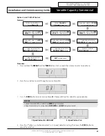
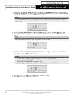
3.  Press the 

PROG

 button 11 x times to enter the Hot Start Settings. 

4.  Press the 

 or  

 buttons to enable/disable the hot start operation. 

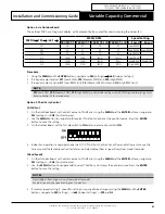
5.  Press the 

PROG

 button to accept the Hot Start setting. 

6.  Press the 

EXIT

 button once to return to the Main Screen. 

15.04.05.  Air Filter Hours

This feature allows the installer to change the alarm time of Filter Notification. By default, the time before the filter 
alarm notification will appear is set to 

200

 hours. This is adjustable from 

0

 to 

990

 hrs. 

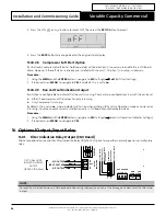
Outdoor Unit CPU Board 

1.   Using  the 

MENU

 and the 

ENTER

 buttons, navigate to 

SEt

 (Settings) 


iduS

 (Indoor Settings) 

→ 

FiL

 (Filter)

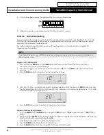
2.   Keep pressing the 

MENU

 button to select the desired filter notification alarm time is shown. By default, alarm 

time is set to 

200

 hrs and is adjustable from 

to

 9900

Note: 

0

 means the Filter Alarm is disabled

3.   Press 

ENTER

 button to confirm the alarm time settings.

4.   Press  the 

BACK

 button twice to go back to the original status display.

NOTE

Setting up “ Air Filter Hours’ is only available through Outdoor Unit CPU Board.

15.04.06.  Economy Damper

This feature allows to set the optional outside air damper opening. The available output signal is from 

0

 to 

10

V. 

Option 1: LC7-2 Wall Control 

1.    Press and hold the 

REPEAT

 and the 

TIMER

 buttons for 3 sec then release to enter Service Menu. The display will 

show the Service Menu

 01

.

2.   Press  the 

 or  

 buttons to scroll to Service Menu 

10

. Press the 

PROG

 button to enter the Service 

Menu 

10

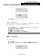
3.   Press  the 

PROG

 button enter economy damper menu.

Содержание PKV290T-L

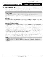
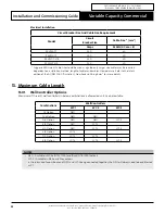
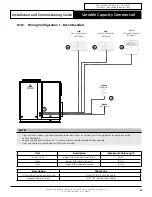
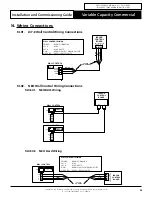
Страница 1: ... That s Actron Variable Capacity Commercial Package Ducted Units Installation and Commissioning Guide PACKAGE MODELS UNDER OVER CONFIGURATION SIDE BY SIDE CONFIGURATION PKV290T T PKV330T T PKV290T L R PKV330T L R Left Air Handing Option shown for illustration purposes only Left Air Handing Option Right Air Handing Option ...

Страница 2: ...3 03 Wiring Configuration 2 Alternate 24 14 Wiring Connections 25 14 01 LC7 2 Wall Control Wiring Connections 25 14 02 NEO Wall Control Wiring Connections 25 14 03 LM RS 2 Optional Sensor Wiring Connections 26 14 04 AERSS Optional Duct Sensor Wiring Connections 26 15 Configuring and Commissioning Setup 27 15 01 Menu and Navigation 27 15 02 Configuring Compressor and Capacity cnFg 27 15 03 Configur...

Страница 3: ...performance high efficiency reliability supply air quality and quiet operation are the prime priorities The units are built with the latest technology advanced variable speed driven compressor EC indoor fans on specific models low noise outdoor fans and an intelligent electronic control For optimum efficiency your air conditioning unit will deliver the right amount of cooling or heating capacity t...

Страница 4: ...hould install and service this air conditioning equipment Improper service or alteration by an unqualified technician could result in significant and major damage to the product or property which may render your warranty null and void Such unqualified service could also lead to severe physical injury or death Follow all safety instructions in this literature and all warning labels that are attache...

Страница 5: ...ases Recover and Recycle Refrigerants Never release refrigerant to the atmosphere It is an offence in Australia to do so Always recover recycle and reuse refrigerants When removing from the system properly contain and identify refrigerants in its dedicated container for proper disposal and or storage Always consider the recycle or reclaim requirements of the refrigerant before beginning the recove...

Страница 6: ...ge Condenser air inlet located on the coil side of the unit requires sufficient airflow clearance for the optimum unit performance Note the conditioned supply air and return air location Ensure sufficient spaces are allocated for these purposes Refer connection and location of condensate drain in the unit drawing and dimensions section of this manual Wiring connections must be in accordance with t...

Страница 7: ...mercial Doc Part No 0525 067 Ver 5 210414 06 Components Overview PACKAGE UNIT COMPONENTS OVERVIEW Left Hand LH Side By Side Configuration shown for illustration purposes only GRILLE PANEL ACCESS EVAP REAR PANEL INDOOR FANS OUTDOOR FANS CONDENSER COIL ASSEMBLY ACCESS EVAP FRONT PANEL LP SWITCH SCROLL COMPRESSOR CRANKCASE HEATER EVAPORATOR COIL ASSEMBLY ELECTRICAL PANEL HP SWITCH ACCESS PANEL COMP E...

Страница 8: ...uide Variable Capacity Commercial OUTDOOR UNIT ELECTRICAL PANEL OVERVIEW FANSPEED CAPACITORS EARTHING BOLTS WITH WASHERS AND NUTS OUTDOOR UNIT CONTROL BOARD CONDENSER MAINS INPUT TERMINAL BLOCKS PFC CAPACITOR CONTROL CIRCUIT BREAKER POWER FACTOR CONTACTOR FAN CIRCUIT BREAKERS CONDENSER FAN CONTACTORS FIRE TRIP TERMINAL BLOCKS 3 PHASE PROTECTION RELAY COMPRESSOR OVERLOAD AND CONTACTOR EMC FILTERS C...

Страница 9: ...nsions are in mm unless specified Refer to corresponding unit dimensional drawing for mounting hole details 2 Service Access Areas and Spaces for Airflow Clearances given are suggested minimum based on the condition that the spaces around the units are free from any obstructions and a walkway passage of 1000mm between the units or between the unit and the outside perimeter is available 3 Minimum s...

Страница 10: ...OOR FANS ID COIL 800 mm SERVICE CLEARANCE COMPRESSOR AND ELECTRICAL 300 mm SERVICE CLEARANCE AND AIRFLOW ALLOWANCE DUCT WORK HEIGHT CLEARANCE 1500 mm 750 mm SERVICE CLEARANCE AND AIRFLOW ALLOWANCE D B A C YY XX CG NOTE Under all circumstances Condenser Air must not recirculate back onto Condenser Coil Keep all clearances free of any obstructions Base Mounting Details 64 1840 64 1409 64 64 76 692 5...

Страница 11: ...sions are in mm unless specified Refer to corresponding unit dimensional drawing for mounting hole details 2 Service Access Areas and Spaces for Airflow Clearances given are suggested minimum based on the condition that the spaces around the units are free from any obstructions and a walkway passage of 1000mm between the units or between the unit and the outside perimeter is available 3 Minimum se...

Страница 12: ...RESSOR AND ELECTRICAL 300 mm SERVICE CLEARANCE AND AIRFLOW ALLOWANCE DUCT WORK HEIGHT CLEARANCE 1500 mm 750 mm SERVICE CLEARANCE AND AIRFLOW ALLOWANCE D B A C OUTDOOR COIL COMP INDOOR COIL INDOOR FANS YY XX CG NOTE Under all circumstances Condenser Air must not recirculate back onto Condenser Coil Keep all clearances free of any obstructions Base Mounting Details 64 1840 64 1409 64 64 76 692 513 U...

Страница 13: ...ions are in mm unless specified Refer to corresponding unit dimensional drawing for mounting hole details 2 Service Access Areas and Spaces for Airflow Clearances given are suggested minimum based on the condition that the spaces around the units are free from any obstructions and a walkway passage of 1000mm between the units or between the unit and the outside perimeter is available 3 Minimum ser...

Страница 14: ...RESSOR AND ELECTRICAL 300 mm SERVICE CLEARANCE AND AIRFLOW ALLOWANCE DUCT WORK HEIGHT CLEARANCE 1500 mm 750 mm SERVICE CLEARANCE AND AIRFLOW ALLOWANCE D B A C INDOOR FANS INDOOR COIL OUTDOOR COIL COMP YY XX CG NOTE Under all circumstances Condenser Air must not recirculate back onto Condenser Coil Keep all clearances free of any obstructions Base Mounting Details 64 1840 64 1409 64 64 76 692 513 U...

Страница 15: ...erved and will take precedence during lifting process Crane Lifting Method Note Crane lifting method is recommended for high rise lifting Fig 1 Connect the loop ends of slings into shackle Provide rubber pads to prevent damage to the unit RUBBER PADS LIFTING POINT Lifting point is located at each corner of the unit 4 Total Size Ø17 5 mm EQUIPMENT REQUIRED FOR CRANE LIFTING 1 x Shackle 2 x Nylon Sl...

Страница 16: ...equipment accessories and plant are sufficiently and safely capable to lift the unit in order to prevent potential damage to property severe personal injury or death Check unit weight and weight distribution points on unit drawing dimensions section NOTES Lifting procedure and unit model shown are suggestions and for illustration purposes only It is highly recommended that installer observe curren...

Страница 17: ...mmercial Doc Part No 0525 067 Ver 5 210414 09 Outdoor Unit Preparation NOTE It is important to remove the shipping blocks before unit operation Step 1 Remove Access Panel as shown below Access Panel Use allen keys to remove the Access Panel Hex Recess 8mm Remove access panel Do not disconnect Earth Cable B Removal Order Pull Out 20mm Pull Down to remove Access Panel Electrical A B A Earth Cable Re...

Страница 18: ... and Commissioning Guide Variable Capacity Commercial Step 2 Remove Shipping Blocks Loosen the set bolts that hold the compressors down onto the unit 4 pcs Slide out shipping block as shown below Loosen Bolts 4 pcs Comp Shipping Blocks GENTLY Push back the Compressor Pull away the Shipping Blocks Step 3 Tighten back the set bolts that hold the compressors down onto the unit 4 pcs Tighten Bolts 4 p...

Страница 19: ...nsure Drain Pipe slopes down from the unit at a minimum of 10mm per meter DETAIL A The top of the Trap must be 125mm below the top of the Evaporator Drain Connection 50mm 4 x PVC Elbow Install a T Piece as an Air Vent for long drain runs Hose Clamps Condensate Tray The top of the Vent must be 50mm higher than the top of the Evaporator Condensate Tray 250mm or high enough to maintain positive Air S...

Страница 20: ...lations and all wiring connections to be as per electrical diagram provided with the unit Confirm that the power supply available is compatible with the unit nameplate ratings The supply power must be within 10 to 6 of the rated voltage as per AS60038 Protect electrical service from over current and short circuit conditions in accordance with the latest edition of the AS NZS 3000 Australian New Ze...

Страница 21: ... WIRING DIAGRAM IS PROVIDED WITH THE UNIT Condenser Side Located at the back of electrical compressor access panel THREE PHASE MAINS WIRING 400 VAC Three Phase Neutral Earth 50Hz DATA CABLE TO WALL CONTROL Cat5E UTP AWG 24 Data Cable 1 2 WALL CONTROL SUB MAINS CIRCUIT BREAKER Field Supplied by Installer DATA CABLE Field Supplied by Installer 2 MAIN SUPPLY FROM DISTRIBUTION BOARD SUB MAIN TO UNIT S...

Страница 22: ...ependent on installation method length of cables and ambient temperature Refer to the latest edition of the AS NZS 3000 Australian New Zealand Wiring Rules for more details 13 Maximum Cable Length 13 01 Wall Controller Options Maximum of three 3 wall controllers in below combinations is allowed on unit See below table Combinations Wall Controllers WC 1 WC 2 WC 3 1st Option NEO 2nd Option NEO NEO 3...

Страница 23: ... OPTIONAL AERSS OPTIONAL NOTES Diagram shown above is a general representation only Refer to individual unit wiring diagram for complete wiring connection details Long runs beside Mains cables or TV antenna cables should be avoided where possible Daisy connection is not allowed for NEO wall controller Item Description Maximum Cable Length 1 to 2a 1 to 2b Indoor PCB to Wall Control 1 and 2 90 m 1 t...

Страница 24: ...LL CONTROL 1 OPTIONAL NOTES Diagram shown above is a general representation only Refer to individual unit wiring diagram for complete wiring connection details Long runs beside Mains cables or TV antenna cables should be avoided where possible ITEM DESCRIPTION MAXIMUM CABLE LENGTH 1 to 2a Indoor PCB to Wall Control 1 optional 100 m 1 to 2c Indoor PCB to Wall Control 3 optional 75m total Daisy Chai...

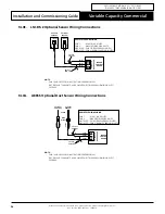
Страница 25: ...BR OR BL BL WH BR WH OR WH BR OR BL BL WH BR WH OR WH INDOOR CONTROL BOARD WALL CONTROL WIRING POWER BROWN ORANGE 485 A BLUE 485 B BLUE WHITE GND BROWN WHITE ORANGE WHITE NOT USED GREEN GREEN WHITE 14 02 NEO Wall Control Wiring Connections 14 02 01 NEO RJ45 Wiring WALL CONTROL TWC 1 12V A B G INDOOR CONTROL BOARD RJ45 WALL CONTROL TWC 2 12V A B G RJ45 WALL CONTROLLER 14 02 02 NEO Hard Wiring WALL ...

Страница 26: ... PURPOSES ONLY CUT OFF AND TERMINATE ANY UNUSED PAIRS TO ENSURE NO WIRING IS LEFT EXPOSED REMOTE SENSOR WIRING PAIR 1 BLUE BLUE WHITE PAIR 2 ORANGE ORANGE WHITE NOT USED PAIR 3 GREEN GREEN WHITE NOT USED PAIR 4 BROWN BROWN WHITE 14 04 AERSS Optional Duct Sensor Wiring Connections AUX SENSOR AUX SENSOR S1 S1 COM COM S2 S2 INDOOR CONTROL BOARD INDOOR CONTROL BOARD REMOTE SENSOR WIRING PAIR 1 BLUE BL...

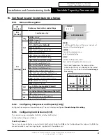
Страница 27: ...not enabled default YES Soft Start enabled run no Indoor Fan and Compressor default YES Compressor only odFs Hi High Start up Speed default Lo Low Start up Speed DISPLAY MENU ENTER BACK OUTDOORBOARD Family and Capacity Table Model PKV290T PKV330T Family Capacity kW 02 29 33 MENU Scroll through the items at the same menu level Increment the value being set ENTER Go into the selected menu Lock in se...

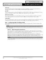
Страница 28: ...ng software or logic in the Outdoor Board but still retaining the safety logic To do this CtrS on the Outdoor Board has to be set to Ct 4 15 04 Configuring Indoor Fan Setting iduS The fan settings may be configured using three options the Condenser CPU Board NEO or LC7 2 Wall Control and Third Party Control NOTES For Configuring Indoor FAN Setting iduS using wall control please refer to respective...

Страница 29: ... adjust the REDUCED AIRFLOW Setting EXIT Service Menu Enter Service Menu Select Menu 03 If required adjust the MED PWM of 3 Speed Setting If required adjust the MED RPM of 3 Speed Setting If required adjust the DEFROST FAN Setting If required adjust the HOT START FAN Setting Procedure 1 Press and hold the REPEAT and the TIMER buttons for 3 seconds then release to enter Service Menu 2 Press the but...

Страница 30: ... PWM or accept the default setting 6 Display shows LOW MED HIGH 3 and FAN With LOW blinking to signify current LOW PWM settings for 3 speed fan Press the or buttons to adjust the PWM setting Then press the PROG button to accept NOTE Default setting and adjustable range may vary depending on indoor models 7 Next display will show the RPM setting for LOW SPEED Press the or buttons to adjust the RPM ...

Страница 31: ...nge limits Refer to Section 15 for more details Option 3 Third Party Control 0 10V Fan 1 On the Outdoor Board set Control Source to Third Party Using the MENU and the ENTER buttons navigate to SEt Settings CtrS Control Source 2 Use the MENU button to navigate to 0 to select Third Party Control as the control source Press the ENTER button to save the setting 3 On the Indoor Board set the first dip ...

Страница 32: ...sioning Guide Option 1 LC7 2 Wall Control 1 Press and hold the REPEAT and the TIMER buttons for 3 seconds then release to enter Service Menu The display will show the Service Menu 01 2 Press the or buttons to scroll to Service Menu 03 Press the PROG button to enter the Service Menu 03 3 Press the PROG button 9 x times to enter the Defrost Fan Settings 4 Press the or buttons to select the desired i...

Страница 33: ...Reduced Airflow Settings 4 Press the or buttons to select the desired indoor fan PWM then press the PROG button to accept The available range is from 20 to 100 OFF means that this function is disabled The sample screen below shows the indoor fan is set to 30 PWM 5 Press the EXIT button once to go back to the original status display Option 2 Outdoor Unit CPU Board 1 Using the MENU and the ENTER but...

Страница 34: ...Using the MENU and the ENTER buttons navigate to SEt Settings iduS Indoor Settings FiL Filter 2 Keep pressing the MENU button to select the desired filter notification alarm time is shown By default alarm time is set to 200 hrs and is adjustable from 0 to 9900 Note 0 means the Filter Alarm is disabled 3 Press ENTER button to confirm the alarm time settings 4 Press the BACK button twice to go back ...

Страница 35: ...t 2 Keep pressing the MENU button to select the desired opening in voltage By default this is set to 0 damper closed Adjustable setting is from 0 to 10V Note that in LED 7 segment display 10 0V will show 100 3 Press ENTER to confirm the desired damper voltage Press BACK button to leave the Menu 4 Press the BACK button three times to go back to the original status display 15 04 07 Fan Continuous ON...

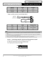
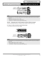
Страница 36: ...icator Settings 2 If required press MENU to navigate to YES 16 Optional Output Input Relay 16 01 Filter Indication Relay Output CMI Board Allows for optional connection for Filter Indication Relay 10A 240V Option to use either normally open or normally close relay OPTIONAL FILTER INDICATION RELAY OUTPUT 240VAC 10A Max R This drawing remains the intellectual property of Actron Engineering Pty Ltd R...

Страница 37: ...feature allows to set the optional outside air damper opening 0 10V To set up see 15 04 06 Economy Damper 0 10V OUTPUT 0 10V INPUT COM COM CMI POT ADJUST AMB SENSOR FILTER INDICATION FAN IN WALL CONTROLLER OUTDOOR AUX SENSOR ECON OUT AUX OUT AUX IN 12V 0 10V 12V COM COM A A S1 0 10V 0 10V B B COM COM COM G G S2 COIL TEMP DISPLAY PWR 0 10V FAN2 OUT 0 10V FAN1 OUT COM 1 COM 2 COM 3 12VDC POWER IN V ...

Страница 38: ...AUX OUT AUX IN 12V 0 10V 12V COM COM A A S1 0 10V 0 10V B B COM COM COM G G S2 COIL TEMP PWR COM 1 COM 2 COM 3 12VDC POWER IN V V ZONE MASTER SECONDARY OFF ON PWM FAN OUTPUT INTERNAL FAN SPEED 1 2 3 4 5 6 7 8 STANDARD DIP SWITCH SETTINGS MANUAL FAN SPEED POT ADJUST OPTIONAL OUTSIDE AIR DAMPER CONTROL OUTPUT OPTIONAL 3RD PARTY FAN CONTROL INPUT HEAT 0 10V G COM 0 10VDC INPUT Input Output Compressor...

Страница 39: ...TY COMPRESSOR CONTROL INPUT NOTE As the compressor turns ON and the Indoor fan signal is not available then indoor fan will start to run on medium PWM speed Indoor fan operation when fan signal is available Compressor ON Indoor fan will run on medium speed Compressor OFF Indoor fan will run on reduce airflow operation 16 04 03 Analogue Input for Fixed Compressor with Fixed Indoor Fan Speed This fe...

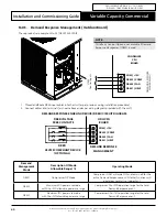
Страница 40: ...allation procedure 2 Connect cables into terminals as shown above and as per wiring diagram provided with the unit DEMAND RESPONSE ENABLING DEVICE DRED CIRCUIT DIAGRAM ODU CPU BOARD DEMAND RESPONSE MANAGEMENT DRED AS4755 COMPLIANT DEVICE OPTIONAL DRED VOLTAGE FREE CONTACTS COM 12V DRM 1 HEAT DRM 2 FAN DRM 3 COMP Demand Management Mode Description Of Mode Allowable Range Operating Mode DRM1 Compres...

Страница 41: ...ing in Wall Controller only control mode 1 or BMS Wall Controller control mode 3 for this function to work Turning the system On and Off by remote method Turning the system On Status 1 The system is Off and the remote switch relay has been left in the open position 1 Close remote switch relay 2 System will start in approximately 1 minute Status 2 The system is Off and the remote switch relay has b...

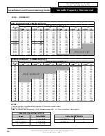
Страница 42: ...106 77 1271 83 1414 99 1551 1800 66 877 70 1000 75 1163 79 1316 88 1497 REDUCED AIRFLOW COMPRESSOR OFF AIRFLOW l s EXTERNAL STATIC PRESSURE Pa 50 100 150 200 250 300 PWM W PWM W PWM W PWM W PWM W PWM W 350 21 333 400 20 295 23 372 450 MOTOR BLOWER LIMIT 22 331 24 381 500 21 291 23 340 26 408 550 22 301 25 371 28 439 600 20 242 23 310 27 406 30 480 650 22 274 25 341 28 418 32 521 700 23 282 26 351 ...

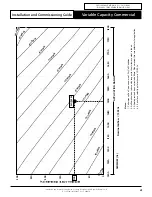
Страница 43: ...RANGE 50 150 250 100 200 300 0 1300 1250 1500 1350 1550 1400 1600 1450 1650 1200 1800 1750 1700 3 0 P W M 4 0 P W M 3 5 P W M 4 5 P W M 5 5 P W M 6 0 P W M 6 5 P W M 7 0 P W M 7 5 P W M 8 0 P W M 8 5 P W M 9 0 P W M 9 5 P W M 9 9 P W M 5 0 P W M 52 PWM Notes 1 P erformance Fan Curve shown is at Dry Coil Condition 2 Airflow should be reduce with respect to the moisture content in the air 3 All data...

Страница 44: ...LOW COMPRESSOR OFF AIRFLOW l s EXTERNAL STATIC PRESSURE Pa 50 100 150 200 250 300 PWM W PWM W PWM W PWM W PWM W PWM W 350 12 174 400 20 289 23 347 450 MOTOR BLOWER LIMIT 22 322 25 393 500 21 287 23 337 26 403 550 22 297 25 370 28 431 600 20 236 23 307 26 378 30 476 650 21 247 25 338 28 415 32 499 700 23 278 26 347 30 446 34 532 750 21 217 24 286 28 380 31 454 35 561 800 22 230 26 316 30 410 33 492...

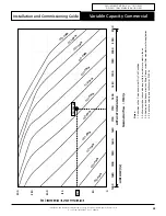
Страница 45: ...should be reduce with respect to the moisture content in the air 3 All data provided does not include filters Please review filter manufacturer for application 4 2 5 m s face velocity point will occur at 2150 l s AIRFLOW l s Nominal Airflow 1750 l s EXTERNAL STATIC PRESSURE Pa 67 PWM 50 150 250 100 200 300 0 1650 1600 1850 1700 1900 1750 1950 1800 2000 APPLICATION RANGE 1550 2100 2050 1500 1450 14...

Страница 46: ...88 1505 1800 67 847 72 1003 76 1133 81 1305 85 1454 93 1582 REDUCED AIRFLOW COMPRESSOR OFF AIRFLOW l s EXTERNAL STATIC PRESSURE Pa 50 100 150 200 250 300 PWM W PWM W PWM W PWM W PWM W PWM W 350 21 266 400 20 280 23 297 450 22 315 24 366 500 MOTOR BLOWER LIMIT 21 273 23 320 26 390 550 22 281 25 348 28 431 600 21 244 24 308 27 383 29 437 650 22 252 25 314 28 389 31 466 700 20 198 24 279 27 347 30 41...

Страница 47: ...flow should be reduce with respect to the moisture content in the air 3 All data provided does not include filters Please review filter manufacturer for application 4 2 5 m s face velocity point will occur at 2100 l s EXTERNAL STATIC PRESSURE Pa AIRFLOW l s Nominal Airflow 1500 l s APPLICATION RANGE 50 150 250 100 200 300 0 1300 1250 1500 1350 1550 1400 1600 1450 1650 1200 1800 1750 1700 8 0 P W M...

Страница 48: ... AIRFLOW l s EXTERNAL STATIC PRESSURE Pa 50 100 150 200 250 300 PWM W PWM W PWM W PWM W PWM W PWM W 350 21 326 400 20 293 22 338 450 21 302 24 379 500 MOTOR BLOWER LIMIT 20 261 23 335 26 406 550 22 295 25 365 27 420 600 20 235 24 324 26 373 29 454 650 22 265 25 329 28 406 31 481 700 20 209 24 293 27 363 30 435 33 517 750 22 237 25 299 29 391 32 468 35 549 800 23 244 27 329 31 423 34 501 37 584 850...

Страница 49: ... 72 PWM 50 150 250 100 200 300 0 5 0 P W M 5 5 P W M 6 0 P W M 6 5 P W M 7 0 P W M 7 5 P W M 8 0 P W M 8 5 P W M 90 PW M 95 PW M 99 PW M 4 5 P W M 1650 1600 1850 1700 1900 1750 1950 1800 2000 APPLICATION RANGE 1550 2100 2050 1500 1450 1400 Notes 1 P erformance Fan Curve shown is at Dry Coil Condition 2 Airflow should be reduce with respect to the moisture content in the air 3 All data provided doe...

Страница 50: ...ted to a label that is fixed to the unit for future reference CAUTION The system of this unit operates with POE oil that rapidly absorbs moisture The maximum time any system can be opened to atmosphere is 15 minutes REFRIGERANT CHARGE DETAILS R 410A Model Refrigerant Charge g PKV290T T 8 500 PKV330T T 10 800 PKV290T L R 9 000 PKV330T L R 12 600 SUBCOOLING AND SUPERHEAT CHARGING METHOD Parameters L...

Страница 51: ...superheat is important for ensuring the evaporator is achieving maximum capacity and avoiding excessive liquid refrigerant returning to the compressor 1 From the R 410A Pressure Temperature Chart record the corresponding Saturated Suction Temperature SST at the given suction pressure 2 Calculate the system superheat using the formula below Superheat SLT SST 3 If superheat is within the range see c...

Страница 52: ... 7 12 1050 9 44 2558 5 51 5 3 19 316 9 13 1084 7 45 2621 8 50 10 7 18 332 6 14 1119 2 46 2686 2 49 16 3 17 348 7 15 1154 6 47 2751 8 48 22 2 16 365 2 16 1190 7 48 2818 5 47 28 2 15 382 3 17 1227 5 49 2886 4 46 34 0 14 399 7 18 1265 2 50 2955 5 45 40 9 13 417 7 19 1303 6 51 3025 7 44 47 8 12 436 2 20 1342 9 52 3097 2 43 54 8 11 455 1 21 1382 9 53 3169 9 42 62 1 10 474 6 22 1423 9 54 3243 7 41 69 6 ...

Страница 53: ...vertently energised Failure to disconnect power before maintenance procedures can result in serious injury and or death Annual Maintenance Checklists Perform general maintenance inspections Perform scheduled start up checks Leak test refrigerant circuits Inspect contacts of all contactors and relays Replace all worn contacts as required Inspect clean and tighten all electrical connections Check fa...

Страница 54: ... coils Straighten bent coil fins with fin comb Prepare the detergent solutions according to the manufacturer s instructions Spray solution at a 90o angle to the coils keeping a minimum nozzle spray angle of 15o with at least a 1800mm distance from the coils and 600 psi pressure Spray leaving air side of the coils first then the air inlet side Allow the solution to stand on the coils for five minut...

Страница 55: ...rosive environment wash panels quarterly with water and neutral detergent solution Wax panels Repair re paint where required Insulation Visual check for insulation conditions Repair replace insulation material Fan Visual check for run out of balance and dust attached Clean off dust as necessary to negate possibility of fan running out of balance Motor Ω Visual check on wiring Insulation resistance...

Страница 56: ...sistance should be more than 1MΩ Heat Exchanger Check for clogging by dust Check for leaks damage Clean air inlet side as necessary Straighten any bent fins using fins comb Condensate Drain Line if available Check for obstructions and free flow of water Clean to eliminate obstructions sludge and check condition of drain line Pour water to ensure free flow Compressor Ω Check for high low pressure M...

Страница 57: ...ATURE SETTINGS AND AMBIENT TEMPERATURE SYSTEM 1 SYSTEM 2 Supply Air Temperature C Supply Air Temperature C Return Air Temperature C Return Air Temperature C Suction Temperature C Suction Temperature C Discharge Temperature C Discharge Temperature C Condenser Coil Temperature C Condenser Coil Temperature C Ambient Temperature C INDOOR FAN SETTINGS Indoor Fan Current Amps Outdoor Fan Current Amps In...

Страница 58: ...THIS PAGE WAS INTENTIONALLY LEFT BLANK ...

Страница 59: ...THIS PAGE WAS INTENTIONALLY LEFT BLANK ...

Страница 60: ...neering Pty Limited ABN 34 002767240 Registered Trade Marks of Actron Engineering Pty Limited ActronAir is constantly seeking ways to improve the design of its products therefore specifications are subject to change without notice Document 0525 067 Ver 5 Issue Date 04 2021 ...

Отзывы: