ACBU011/ACLU011 User Manual
ACBU011 / ACLU011
UNIVERSAL
REDUNDANCY CONTROLLER
USER MANUAL
Страница 1: ...ACBU011 ACLU011 User Manual ACBU011 ACLU011 UNIVERSAL REDUNDANCY CONTROLLER USER MANUAL ...
Страница 2: ...Controller 5 Technical Specifications of LNB LNA Redundancy Controller 7 III Redundancy Controller M C Connection Instructions 9 Redundancy Controller 19 pin Connection for a PC Laptop 9 Redundancy Controller Connection for a Waveguide Switch 12 IV Redundancy Controller Connection via Terminal 13 V Redundancy Controller connection via Ethernet 20 ...
Страница 3: ...ts Operate in automatic or changeover mode Display status information of unit in the receive chains Manual and automatic operation of the receive chains Visual indications of the on line chain for receive systems Visual indication latching of chain alarms Remote M C of chain changeover and unit functions via RS 232 485 422 built in TSP IP Ethernet interface optional Power supply voltage regulation...
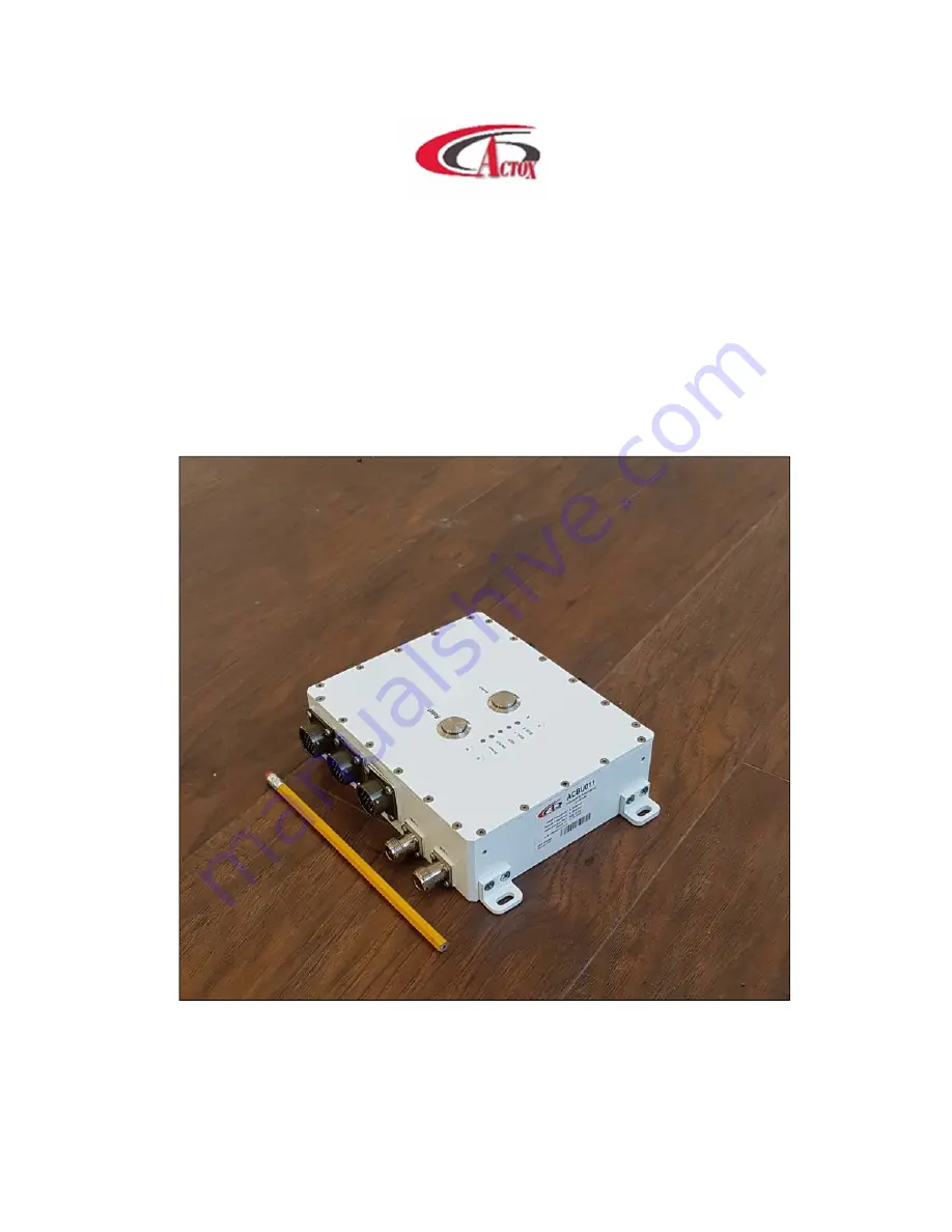
Страница 4: ...011 User Manual Page 4 of 23 II Block Overview Mechanical Drawing The appearance of the Redundancy Controller and its connectors are displayed on the below Figure 1 Figure 1 Redundancy Controller Mechanical Drawing ...
Страница 5: ... Manual Page 5 of 23 Technical Specifications of BUC Redundancy Controller The technical specifications of BUC Redundancy Controller are displayed on the below figure 2 Figure 2 Technical Specifications Connection Diagram ...
Страница 6: ...ancy Controller to laptop PC connection provided via 19 pin cable from the Redundancy side and RS 232 and or RS 485 from the PC side Redundancy M C to Unit 1 and Unit 2 connection provided via 19 pin cable on Redundancy side and two 19 pin on the other side And from the other side L band F or N connector for BUC connection with modem provided via coaxial cable It also can provide power supply from...
Страница 7: ...Manual Page 7 of 23 Technical Specifications of LNB LNA Redundancy Controller The technical specifications of the LNB LNA Redundancy Controller are displayed on figure 3 Figure 3 Technical Specifications Connection Diagram ...
Страница 8: ...ndancy Controller to laptop PC connection provided via 19 pin cable from the Redundancy side and RS 232 and or RS 485 from the PC side Redundancy M C to Unit 1 and Unit 2 connection provided via 19 pin cable on Redundancy side and two 19 pin on the other side And from the other side L band F or N connector for BUC connection with modem provided via coaxial cable It also can provide power supply fr...
Страница 9: ...tion for a PC Laptop Redundancy Controller connection to PC carried by cable with 19 pin female connector fig 4 on the one side and RJ45 fig 4 2 two DB9 fig 4 1 female connectors RS232 and RS485 on the other side Figure 4 19 pin connector configuration Figure 4 1 DB9 connector configuration Figure 4 2 RJ45 connector configuration ...
Страница 10: ...ace pin Pin Name 19 pin Connector RJ45 3 RX C 6 RX P 1 TX L 2 TX N R75_TX NC R75_RX NC GNDISO A GNDISO RS485 2 A S 1 B F 4 Z H 3 Y T 5 GNDISO V GNDISO NC NC NC NC GNDISO G RS232 5 GNDISO 2 RS232TX J 3 RS232RX E Figure 4 3 Redundancy 19 pin connector for a PC Laptop ...
Страница 11: ...n Unit 1 Ethernet M MUTE1 17 NC B ALARM1 18 NC E RS232_TX1 11 NC J RS232_RX1 16 NC G GNDISO 12 NC 20 NC V GNDISO NC 12 NC 20 T RS232_TX2 NC 11 S RS232_RX2 NC 16 H MUTE2 NC 17 K ALARM2 NC 18 RX_P 2 2 3 RX_N 6 6 6 TX_P 7 7 1 TX_N 8 8 2 Figure 4 4 Redundancy 19 pin cable to Unit 1 and Unit 2 ...
Страница 12: ...with 19 pin female connector on the both sides Waveguide Switch schema is displayed on Figure 5 Figure 5 Switch input pins From Redundancy Interface Pin Pin Name From Switch Pin A Ind Pos 1 A B Ind Com B C Ind Pos 2 C D Pos 1 D E Monitor Com E F Pos 2 F G NC G H NC H J NC J K NC K L NC L M NC M N NC N P NC P R NC R S NC S T NC T U NC U V NC V Figure 5 1 Switch interface ...
Страница 13: ...tart window Figure 6 Start window On the top of the window are situated the following menu tabs INTERFACE consist information about redundancy connection Serial port select COM port you want to connect to Exit select to quit program STATUS push button Read to get current information about redundancy connector status You will see next window displayed in Figure 6 1 ...
Страница 14: ...b PARAMETERS WS STATUS Displays current position of the waveguide switch fig 6 2 Current position status could be OK other could be ERROR Figure 6 2 WS RF paths positions REF MODE INTERNAL Displays status of reference frequency mode OK if Internal mode ERROR if External mode POWER STATUS Displays power or amperage appliance of the BUC Power or Amperage is in OK if its value is within acceptable li...
Страница 15: ...ATUS Displays port connection status SERIAL STATUS is a digital signal transmitted via M C cable SERIAL STATUS is in OK if correct port connected in ERROR if port failure and DISABLED if port didn t connect SERIAL PORT COMMUNICATION Displays Redundancy communication with PC status To change Redundancy controller system settings push button PARAMETERS You will see next window Figure 6 3 Redundancy ...
Страница 16: ...tch motor voltage value Minimum voltage Set the minimum value for Redundancy controller supply This value can t be lower than WS Motor Voltage value for proper Switch work can t be lower than minimum permissible working voltage for BUC or LNB Minimum voltage value can t be lower than 12V Maximum voltage Set the maximum value for Redundancy controller supply This value can be higher than power supp...
Страница 17: ...t supply parameters are in setting limits If supply parameters are correct device feeds in accordance to the established priority 0 the highest priority 2 the lowest priority Serial Interface Set parameters of Redundancy connection with BUC via M C interface Choose port you want to enable and set it parity speed and bit rare Bit rate speed depends on BUC s version Alarm Enable Enable or disable su...
Страница 18: ...ype in the new login and password in appropriate cells and push button Set New to send this configuration to the device or push button Set Default to restore default login 123456 and password 123456 Push button Net Configurations to open web parameters Figure 6 7 Net Configuration window Set manually parameters you want to change and push button Send to device ...
Страница 19: ...In the latest version of the software you can change waveguide position Open inset WS on the menu push button Set Position You will see next window Figure 6 8 WS Position window Push button WS Position in the window to change waveguide position ...
Страница 20: ...net switch on the device and open the internet browser In the address line type in IP address of your Redundancy by default IP address 192 168 1 249 and you will see log in window fig 7 Figure 7 Log in window Type in login by default 123456 and password by default 123456 to log in to see Redundancy Status fig 7 1 Figure 7 1 Redundancy Status page ...
Страница 21: ...e ERROR if no reference frequency Internal frequency turns off in this mode You can switch this parameter on the Autodetect mode if your Redundancy has its own Internal reference frequency POWER STATUS Displays power or amperage appliance of BUC Power or Amperage is in OK if it s value within acceptable limits and ERROR if out of limits Device turns off BUC if power or amperage parameters are out ...
Страница 22: ...ust be lower than minimum power current value for BUC or LNB but can t be lower than 0 02 A Maximum Power Current Set the maximum Power or Current for each BUC and LNB It must be higher than maximum power current value for BUC or LNB but can t be higher than 5 A Motor DC Set the nominal voltage value that written in specifications for your switch device REF Mode Chose between Autodetect and Extern...
Страница 23: ...the new login or password and push the button Set Login Password to apply changes Net Configuration field Read or change internet address of the device here and push button Set Address to apply changes Push button Redundancy Status to return status page __________________________________________________________________ NOTE All changeable values must be installed manually _________________________...