ABD200KX User Manual
Page 1 of 35
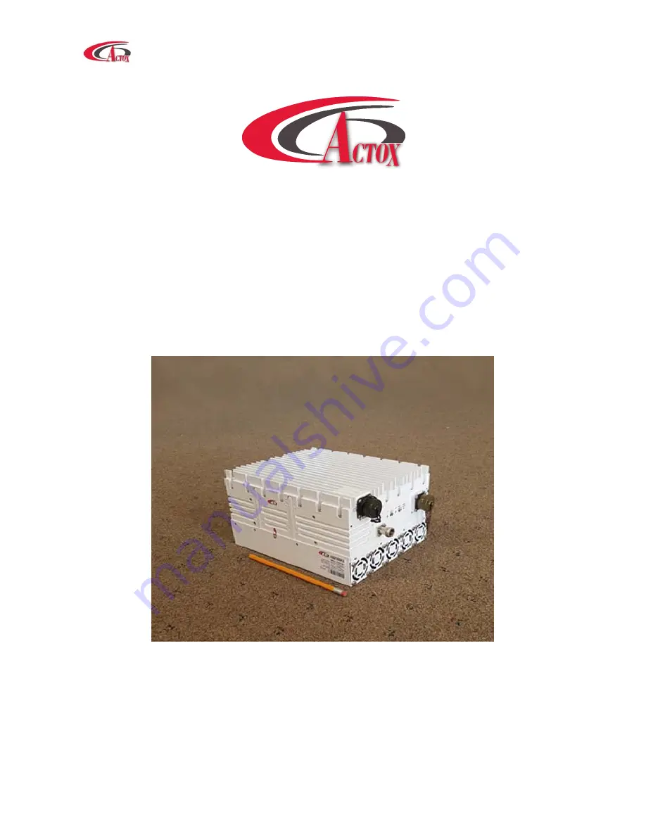
ABD200KX / ABD200KXF
200 W Extended Ku-Band BUC
USER MANUAL
Страница 1: ...ABD200KX User Manual Page 1 of 35 ABD200KX ABD200KXF 200 W Extended Ku Band BUC USER MANUAL...
Страница 2: ...description 8 Considerations Securing the Block Up Converter Installing the Block Up Converter 9 LED Indicators Connector Pin Assignment 10MHz Reference Powering Options Setting L O Setting Tx Rx Freq...
Страница 3: ...rocedure Block Up Converter Cooling System Preventive Maintenance Performance Check Troubleshooting Out of Warranty Repair Appendix 1 Technical Specifications 18 Appendix 2 Mechanical Drawing 19 Appen...
Страница 4: ...tion and maintenance of the ABD200KX BUC It contains information intended for engineers technicians and operators working with the block up converter To make inquiries or to report errors of fact or o...
Страница 5: ...terized by unparalleled durability and dependability This is the smallest and lightest 200W L To Ku Band Block Up Converter and is designed to be mounted on the feed horn The unit is ideal for portabl...
Страница 6: ...oper packaging please notify Actox Corporation immediately Equipment Damage or Loss Actox Corporation is not responsible for damage or loss of equipment during transit For further information contact...
Страница 7: ...f or others The block up converter must be installed in accordance with the conditions and recommendations contained in the following sections Safety Precautions Carelessness or mishandling of the blo...
Страница 8: ...n terminated with a load of VSWR at 2 1 unless otherwise specified All RF specifications shall be met within five minutes after applying power except gain flatness which shall be met after a warm up p...
Страница 9: ...antenna to the satellite Lightning arrestors should be used at the site to protect personnel and equipment Preparation Mounting Considerations Optional Mounting Brackets are available that will facili...
Страница 10: ...10MHz is Absent 10MHz LED Green Blinking Internal 10MHz Reference M C Connection for 19 Pin 19 pin conn 9 pin conn GND G 5 TX 232 J 2 RX 232 E 3 The following should be set on the COM Port Baud Rate 9...
Страница 11: ...e short Pin M Pin V Monitor TTL ALARM_IZ B Summary Fault Alarm TTL Low Monitor Analog 0 to 5V P_OUT_OUT D U 4 5V 0 5V Pmax Monitor Control GND WIRE_GND V 10MHz Reference The BUC must receive a stable...
Страница 12: ...h calibrated insertion loss up to 15GHz 40 dB attenuator High Power to match HPA output Assortment of cables connectors and adapters calibrated up to 18 GHz Ensure that the BUC TX output power is disa...
Страница 13: ...carried out in dry conditions free of salt spray or excessive humidity This will eliminate the possibility of moisture and other foreign substances from entering the output waveguide flange Only auth...
Страница 14: ...er of the RF Amplifier provide the necessary gain and low insertion loss The amplified signal is transmitted through the output waveguide section to a satellite up link system Monitor and Control opti...
Страница 15: ...l result in personal injury Safe and careful installation of this block up converter will eliminate the possibility of accidents and provide years of top performance Verify the antenna feed waveguide...
Страница 16: ...ure to observe this precaution may result in personal injury or death This includes the removal of any RF power originating from other system components When the block up converter is in the hot stand...
Страница 17: ...he return loss From the output power measurements determine rated output power Record value on a test data sheet Measure the Two tone Inter modulation Suppression using two equal signals separated by...
Страница 18: ...10 MHz sine wave input power 5 to 5 dBm input port Phase noise Exceeds Intelsat s standard IESS308 309 55 dBc Hz max 10 Hz 65 dBc Hz max 100 Hz 75 dBc Hz max 1 KHz 85 dBc Hz max 10 KHz 95 dBc Hz max 1...
Страница 19: ...ABD200KX User Manual Page 19 of 35 Appendix 2 Mechanical Drawing...
Страница 20: ...be sent via email to the following address Fax 1 866 888 6087 Email mark_moore actox com For additional information please contact our customer service department at 619 906 8893 or 1 866 888 6087 Act...
Страница 21: ...4 06 06 TT TT ZZ 7F TT TT Device temp in C 273 ZZ CRC Temp 0x0102 0d258 273 15 C 2 cmd 7E FF 02 06 06 02 7F reply 7E FF 84 06 06 01 34 B1 7F Temp 0x0134 0d308 273 35 C Get Power Supply Temperature 7E...
Страница 22: ...nd Packet format Explanation Possible replies Interpretation Examples Get Power Supply Current 7E FF 02 06 11 15 7F Query device for power supply current Update PS Current 7E FF 84 06 11 PP PP ZZ 7F C...
Страница 23: ...0d105 0x0069 Set Low Power Alarm Threshold 7E FF 14 10 10 TT TT ZZ 7F Set low power alarm threshold Note zero value means low power alarm disabled ACK NACK TT TT Low power threshold in 10 x dBm ZZ CRC...
Страница 24: ...se element ACK command high nibble 0xE Acknowledge a received packet NACK command high nibble 0xF Reject a received packet Not ACKnowledge Data1 Datan contains the packet payload The value of the data...
Страница 25: ...database element 0x0606 from the Booster device address 0x0F the command is Example Only 7E FF 02 06 06 02 7F Dest Src 0xFF CMD Len 0x02 1111 1111 0000 0010 XOR 1111 1101 Data1 0x06 0000 0110 XOR 1111...
Страница 26: ...PC Laptop BUC connection to PC carried by cable with 19 pin female connector fig 1 on the one side and RJ45 fig 2 two DB9 fig 3 female connectors RS232 and RS485 on the other side Figure 1 1 19 pin co...
Страница 27: ...n name From BUC pin NC NC R NC NC U NC NC K Ethernet 3 RX_P C 6 RX_N P 1 TX_P L 2 TX_N N RS 485 5 GNDISO A 4 TX_B H 3 TX_A T 1 RX_B F 2 RX_A S RS 232 5 GNDISO G 2 TX_RS 232 J 3 RX_RS 232 E NC MUTE_IN...
Страница 28: ...rial Number Read only Factory set Each unit has a unique number Below the head you can find two tabs Monitor and Settings Monitor Tab Tab Monitor provides online telemetry of BUC Output Power Display...
Страница 29: ...nge according to the established L O o Green color frequency 26550Hz o Blinking green color frequency 27400Hz o Yellow color frequency 28050Hz o Blinking yellow color 29050HZ SSPA indicates Solid Stat...
Страница 30: ...Parameters IP Address Configurable Factory default 192 168 1 250 Default Gateway Configurable Factory default 192 168 1 1 Port Configurable Factory default 80 Subnet Mask Configurable Factory default...
Страница 31: ...efault enable Ref Button Changes button functions o Led sw switch on off LED s on dashboard o Ref sw switch on off auto detect function if BUC works on internal reference frequency Configurable Factor...
Страница 32: ...u will see next page Figure 3 1 Start Page For log in type your login and password in appropriate fields There are two access levels User and Admin By default User s access level ID Login User Passwor...
Страница 33: ...n configure options from the Monitor tab MUTE to change mode from MUTE to UNMUTE click button Switch 10MHZ to change mode from INTERNAL to EXTERNAL click button Switch L O choose right Local Oscillati...
Страница 34: ...status IP Address Subnet Mask Default Gateway Port and MAC Address connection speed for RS232 and RS485 ports and BUC address Right panel designed to change login configurations such as Name and Pass...
Страница 35: ...st reboot your device New Community you can set password for SNMP browser Without this password you wouldn t get access to BUC via SNMP browser Type new password in the green field In field Confirm Ne...