Acnodes PC8719 Скачать руководство пользователя страница 1

PC 8719


Industrial  Panel  PC


User Manual 


PC8719

: 19” Industrial Touch Panel PC with  

Core i3-2330E 2.2GHz Processor 


14628 Central Ave, 

Chino, CA 91710 

tel:909.597.7588, fax:909.597.1939 


© Copyright 2013 Acnodes, Inc. 

All rights reserved. Product description and product specifications 
are  subject  to  change  without  notice.  For  latest  product  information, 

please  visit  Acnodes’  web  site  at  www.acnodes.com. 


Содержание PC8719

Страница 1: ...2GHz Processor 14628 Central Ave Chino CA 91710 tel 909 597 7588 fax 909 597 1939 Copyright 2013 Acnodes Inc All rights reserved Product description and product specifications are subject to change wi...

Страница 2: ...lass A computing device pursuant to FCC Rules which are designed to provide reasonable protection against such interference when operated in a commercial environment Operation of this equipment in a r...

Страница 3: ...damage Avoid your system from static electricity on all occasions Prevent electric shock Don t touch any components of this card when the card is power on Always disconnect power when the system is no...

Страница 4: ...2 1 Mainboard Specifications 11 2 2 Jumpers Setting and Connectors 14 Chapter 3 BIOS Setup 3 1 Operations after POST Screen 30 3 2 BIOS SETUP UTILITY 30 3 3 System Overview 31 3 4 Advanced Settings 3...

Страница 5: ...iver 62 4 4 Realtek HD Audio Driver Installation 66 4 5 Microsoft NET Framework 3 5 Service 68 Chapter 5 Touch Screen Installation 5 1 Introduction to Touch Screen Controller Board 70 5 2 Windows 2000...

Страница 6: ...1 x Mic in Line Out 1 x DC Power 3 Pin terminal block connector 1 x 2 Pin remote power switch connector 2 x LED indication By cable 1 x RS 232 COM4 1 x RS 422 485 default RS 485 COM3 1 x CF slot 1 x R...

Страница 7: ...nput DC 9 32V Mechanical Construction Steel black IP Rating Front Panel IP65 Mounting Panel mount Dimensions WxHxD 19 06 x 15 75 x 4 69 Environmental Operating Temperature 0 50 C Storage Temperature 2...

Страница 8: ...1 2 Dimensions Figure 1 1 Dimensions of PC 8719...

Страница 9: ...hard disk drive and 1 x CF space for data storage support DDR3 memory up to 16G support rich i O wide range 9 32V DC input and also provide 1 x PCIe x 16 slot it can ensure simplified connectivity to...

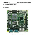
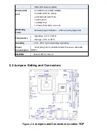
Страница 10: ...Chapter 2 Hardware Installation 2 1 Mainboard Specifications Introduction Figure 2 1 Mainboard Overview...

Страница 11: ...To satisfy the special needs of high end customers ADOtec designed 120Pin PCIe x16 and 40Pin PCIe x1 expansion interface The product is widely used in various sectors of industrial control 2 1 Specifi...

Страница 12: ...Digital I O 8 bit digital I O by Pin header by MIO2 4 bit digital Input 4 bit digital Output Battery Support CR2477 Li battery by 2 pin header Support CR2032 Li battery option Audio Support Audio via...

Страница 13: ...t 1 x HDMI Port 1 x Audio Ports Mic Line out Software programmable 1 255 second by Super I O Operating 20 to 70 Storage 40 to 85 Humidity 10 90 non condensing operating Power Consumption 12V 3 80A Int...

Страница 14: ...ar a Turn off the system and unplug the power cord from the power outlet b To clear the CMOS settings use the jumper cap to close pins1 and 2 for about 3 seconds then reinstall the jumper clip back to...

Страница 15: ...AT Power 4 PS_ON 2 0mm Pitch 1X3 Pin Header ATX Power and Auto Power on jumper setting PS_ON Mode Close 1 2 Auto Power on Default Close 2 3 ATX Power 5 DCIN 5 08mm Pitch 1x3 Pin Connector DC9V DC32V...

Страница 16: ...Ground Pin3 ATX 5VSB 8 DC_OUT 2x2 Pin Connector DC12V and DC5V System power output connector Pin Power output Pin1 DC 12V Pin2 Ground Pin3 Ground Pin4 DC 5V 9 U1 Socket G2 installing the 2nd GEN inte...

Страница 17: ...2 VGA1 CRT 2 0mm Pitch 2X5 Pin Header Video Graphic Array Port Provide 2x5Pin cable to VGA Port Signal Name Pin Pin Signal Name CRT_RED 1 2 Ground CRT_GREEN 3 4 Ground CRT_BLUE 5 6 Ground CRT_H_SYNC 7...

Страница 18: ..._N LA_D1_P 16 15 LA_D1_P Ground 18 17 Ground LB_D2_N 20 19 LA_D2_N LB_D2_P 22 21 LA_D2_P Ground 24 23 Ground LB_CLK_N 26 25 LA_CLK_N LB_CLK_P 28 27 LA_CLK_P Ground 30 29 Ground LVDS_DDC_DATA 32 31 LVD...

Страница 19: ...tion Close 1 2 COM1 RI Ring Indicator default Close 3 4 COM1 Pin9 5V option Close 5 6 COM1 Pin9 12V option 21 JP1A 2 0mm Pitch 2x10 Pin Header COM1 jumper setting it provides selectable RS232 or RS422...

Страница 20: ...RTS Request To Send 8 CTS Clear To Send 9 JP1 select Setting RI 5V 12V RS422 option Pin Signal Name 1 422_R 2 422_R 3 422_T 4 422_T 5 Ground 6 NC 7 NC 8 NC 9 NC RS485 option Pin Signal Name 1 NC 2 NC...

Страница 21: ...3 TXD Transmit Data 4 DTR Data Terminal Ready 5 Ground 6 DSR Data Set Ready 7 RTS Request To Send 8 CTS Clear To Send 9 JP2 select Setting RI 5V 12V 25 COM5 2 0mm Pitch 2X5 Pin Header COM5 Port standa...

Страница 22: ...S JP3select Setting RI 5V 12V 9 10 NC 28 USB_LAN1 USB_LAN2 USB4 USB5 USB6 USB7 Double stack USB type A Rear USB connector it provides up to 4 USB2 0 ports speed up to 480Mb s Each USB Type A Receptacl...

Страница 23: ...ource via a Line in cable MIC is the port for microphone input audio Signal Name Pin Pin Signal Name SPK_OUTL_P 1 2 SPK_OUTR_P SPK_OUTL_N 3 4 SPK_OUTR_N FRONT_JD 5 6 LINE1_JD LINE_IN_L 7 8 LINE IN R M...

Страница 24: ...IE card 30mmx30mm assemble H2 for mini PCIE card 30mmx50 95mm assemble 38 BUZZER1 Onboard buzzer 39 MIO1 DF13 40P Connector For expand output connector It provides two RS232 ports or one RS485 port th...

Страница 25: ...16 15 PCH_GPIO58 GPIO_IN3 GPIO_OUT4 PCH_GPIO71 18 17 PCH_GPIO75 GPIO_IN4 PS2_Mouse 5V_S5_USB 20 19 Ground PS2_K B PS2_MSDATA 22 21 PS2_KBDATA PS2_MSCLK 24 23 PS2_KBCLK USB3 5V_S5_USB 26 25 5V_S5_USB...

Страница 26: ...2 KB MS PS 2 keyboard and mouse port the port can be connected to PS 2 keyboard and mouse via a dedicated cable for direct used Pin25 40 USB0 USB1 USB2 USB3 Front USB connector it provides 4 USB ports...

Страница 27: ...CFAST option CFAST Card socket it is located at the bottom of the board and serves as an insert interface for CFAST card 45 SIM option SIM Socket 7Pin Support SIM Card devices 46 M_SATA1 50 95mmx30mm...

Страница 28: ...TB 525E161 connect to ASB M8671T PCIE_16X connector PCIE_16X is located at the top It provides one PCIE X16 slot...

Страница 29: ...e POST screen displayed for the first time is as follows and includes basic information on BIOS CPU memory and storage devices 3 2 BIOS SETUP UTILITY Press Delete key to enter BIOS Setup utility durin...

Страница 30: ...er Select Charge Opt F1 General Help F2 Previous Values F3 Optimized Defaults F4 Save and Exit ESC Exit Version 2 10 1208 Copyright C 2010 American Megatrends Inc 3 3 System Overview Main Settings Apt...

Страница 31: ...to 59 System Date Set the system date the date format is Day Note that the Day automatically changes when you set the date Month 01 to 12 Date 01 to 31 Year 1998 to 2099 3 4 Advanced Settings Aptio S...

Страница 32: ...merican Megatrends Inc 3 4 1 PCI Subsystem Settings PCI Bus Driver Versio V2 03 00 PCI ROM Priority EFI Compatible ROM Legacy ROM PCI Common Settings PCI Latency Timer 32 PCI Bus Clocks 64 PCI Bus Clo...

Страница 33: ...s 4096 Bytes Maximum Read Request Auto 128 Bytes 256 Bytes 512 Bytes 1024 Bytes 2048 Bytes 4096 Bytes PCI Express Link Settings ASPM Support Disabled Enabled WARNING Ebabling ASPM may cause some PCI E...

Страница 34: ...Signature 206a7 Microcode Patch 25 Max CPU Speed 2400 MHz Min CPU Speed 800 Mhz Processor Cores 2 Intel HT Technology Supported Intel VT x Technology Supported L1 Data Cache 32 KB x 2 L1 Code Cache 3...

Страница 35: ...uration SATA Controller S Enabled Disabled SATA Mode Selection IDE AHCI RAID SATA Test Mode Disabled Enabled Serial ATA Port 0 Empty Software Preserve Unknown Serial ATA Port 1 Empty Software Preserve...

Страница 36: ...l Sku Firmware ME Firmware SKU Unidentified ME Firmware Update Configuration ME FW Image Re Flash Disabled Enabled 3 4 7 USB Configuration USB Configuration USB Devices 1 keyboard 2 Hubs Legacy USB Su...

Страница 37: ...onfiguration COM4 Configuration COM5 Configuration COM6 Configuration 3 4 9 HW Monitor PC Health Status System temperature 48 C CPU temperature 52 CPU Fan Speed 6000 RPM VCORE 1 145V 12V 11 685 V 3 3V...

Страница 38: ...ds Inc Main Advanced Chipset Boot Security Save Exit System Agent SA Configuration PCH IO Configuration System Agent SA Parameters Select Screen Select Item Enter Select Charge Opt F1 General Help F2...

Страница 39: ...bled Enabled Disabled Enabled Graphics Configuration IGFX VBIOS Version 2120 IGFX Frequency 650 MHz Graphics Turbo IMON Current 31 Primary Display Internal Graphics GTT Size Aperture Size DVMT Pre all...

Страница 40: ...mary IGFX Boot Display LCD Panel Type VBIOS Default CRT DVI LVDS HDMI 1024 X 768 LVDS1 640 X 480 LVDS 800 X 600 LVDS 1280 X 1024 LVDS 1400X1050 RB LVDS1 1400X1050 LVDS2 1600 X 1200 LVDS 1366 X 768 LVD...

Страница 41: ...400 x 1050 SDVO LFP 1600 x 1200 SDVO LFP Auto Off Force Scaling PWM Inverted PWM Normal GMBus Inverted GMBus Normal BIA Auto Disabled Level 1 Level 2 Level 3 Level 4 Level 5 Spread Spectrum clock chip...

Страница 42: ...0p60 HDTV_STD_CEAEIA_7702A_480p60 HDTV_STD_CEAEIA_7702A_480i60 VBIOS Default NTSC_M NTSC_M_J NTSC_433 PAL_B PAL_G PAL_D PAL_H PAL_I PAL_M PAL_N SECAM_L SECAM_B SECAM_D SECAM_G SECAM_H SECAM_K HDTV_STD...

Страница 43: ...A eDP Port D 18 Bit 24 Bit DMI Configuration NB PCIe Configuration PEG0 Not Present PEG0 Gen X Auto Gen1 Gen2 PEG1 Not Present PEG1 Gen X Auto Gen1 Gen2 PEG2 Not Present PEG2 Gen X Auto Gen1 Gen2 PEG...

Страница 44: ...n 1 2 10 Memory Frequency 1333 Mhz Total Memory 2048 MB DDR3 DIMM 0 2048 MB DDR3 DIMM 1 Not Present DIMM 2 Not Present DIMM 3 Not Present CAS Latency tCL 9 Minimum delay time CAS to RAS tRPmin 9 Row P...

Страница 45: ...ed Generation off Memory Remap Channel A DIMM Control Disabled Dynamic 1GB 1 25GB 1 5GB 1 75GB 2GB 2 25GB 2 5GB 2 75GB 3GB 3 25GB Auto 1N Mode 2N Mode Enabled Disabled Disabled Enabled Enabled Disable...

Страница 46: ...EXTTS via TS on Board EXTTS via TS on DIMM Virtual Temperature Sensor VTS Enabled Disabled Disabled Enabled Disabled Enabled Disabled Enabled Disabled Enabled GT Power Management Control GT Info GT2 0...

Страница 47: ...essages Force BIOS Interrupt 19 Capture Enabled CSM Support Enabled Boot Option Priorities Boot Option 1 SATA PM Hitachi Hard Drive BBS Priorities Number of seconds to Wait for setup Activation key 65...

Страница 48: ...ss to Setup and is Only asked for when entering Setup If ONLY the User s password is set then this Is a power on password and must be entered to Is a power on password and must be entered to Boot or e...

Страница 49: ...each time you enter BIOS setup This will prevent unauthorized persons from changing your system configurations Also the feature is capable of requesting users to enter the password prior to system bo...

Страница 50: ...it Save Exit Setup save Configuration and exit Yes No Discard Changes and Ext Exit Without Saving Quit without saving Yes No Save Changes and Reset Save reset Save Configuration and reset Yes No Disca...

Страница 51: ...Restore user Defaults Yes No Restore User Defaults Restore User Defaults Yes No Launch EFI Shell from filesystem device WARNING Not Found ok...

Страница 52: ...de Intel QM67 Chipset Driver Intel R VGA Chipset Driver Intel R Network Adapter Realtek ALC662 Audio Codec Driver Microsoft NET Framework 3 5 Service Touch Panel Driver Installation instructions are g...

Страница 53: ...4 1 Intel Chipset Driver To install the Intel chipset driver please follow the steps below Step 1 Access Industrial Panel PC Select Intel QM67 Chipset Driver Step 2 Click Next to setup program...

Страница 54: ...Step 3 Read the license agreement Click Yes to accept the terms of the license agreement Step 4 Click Next to continue...

Страница 55: ...Step 5 Click Next Step 6 Select Yes I want to restart this computer now Click Finish then remove any installation media from the drives...

Страница 56: ...4 2 Intel R VGA Chipset Driver To install the VGA drivers follow the steps below to proceed with the installation Step 1 Select Intel R VGA Chipset Driver Step 2 Click Yes to continue...

Страница 57: ...Step 3 Click Next to continue setup program Step 4 Read the license agreement Click Yes to accept the license agreement...

Страница 58: ...Step 5 Click Next Step 6 Click Continue Anyway...

Страница 59: ...Step 7 Click Continue Anyway Step 8 Click Next...

Страница 60: ...Step 9 Select Yes I want to restart this computer now Click Finish...

Страница 61: ...k Adapter Driver To install the Intel 82574L Network adapter Driver please follow the steps below Step 1 Select Intel R Network Adapter Step 1 Wait for extracting the files then click Next to continue...

Страница 62: ...Step 4 Select Drivers Intel R PROSet for Windows Device Manager Advanced Network Step 3 Read the license agreement Select I accept the terms in the license agreement then click Next to continue...

Страница 63: ...Services Click Next to continue Step 5 Click Install to begin the installation Step 6 Click Finish to compete the installation...

Страница 64: ......

Страница 65: ...Installation To install the Realtek High Definition HD Audio driver please follow the steps below Step 1 Select Realtek ALC662 HD Audio Codec Driver from the list Step 2 Wait for extracting the files...

Страница 66: ...Step 3 Click Next to continue the installation Step 4 Select Yes I want to restart my computer now then click Finish...

Страница 67: ...stall the Realtek High Definition HD Audio driver please follow the steps below Step 1 Select Microsoft NET Framework 3 5 Service Step 2 Select I have read and ACCEPT the terms of the License Agreemen...

Страница 68: ...Step 3 Click Exit to complete the installation...

Страница 69: ...verter built in to make the total printed circuit board denser circuit diagram also designed for 12 bit ADC for optional There are two connectors on this board one connector is for 4 5 8 wire touch sc...

Страница 70: ...plugged in before the machine is turned on When the system first detects the controller board a screen appears that shows Unknown Device Do not use this hardware wizard Press Cancel Step 2 Insert the...

Страница 71: ...Step 4 Read the license Agreement Click I agree to agree the license agreement Step 5 Choose the folder in which to install PenMount Windows Universal Driver Click Install to start the installation...

Страница 72: ...Step 6 Wait for installation Then click Next to continue Step 7 Click OK...

Страница 73: ...Step 8 Click Finish to compete installation...

Страница 74: ...the PenMount Control Panel are Device Multiple Monitors Tools and About which are explained in the following sections Device In this window you can find out that how many devices are detected on your...

Страница 75: ...Use command mode call calibration function this can uses Standard 4 9 16 or 25 points to calibrate E g Please run ms dos prompt or command prompt c Program Files PenMount Universa Driver Dmcctrl exe...

Страница 76: ...o start calibration procedure NOTE The older the touch screen the more Advanced Mode calibration points you need for an accurate calibration Use a stylus during Advanced Calibration for greater accura...

Страница 77: ...nt Control Panel and select Tools then Click Advanced Calibration Step 4 Select Device to calibrate then you can start to do Advanced Calibration NOTE Recommend to use a stylus during Advanced Calibra...

Страница 78: ...Setting...

Страница 79: ...About This panel displays information about the PenMount controller and driver version...

Страница 80: ...e note once you turn on this function the rotating function is disabled Requirements Before using the Multiple Monitors function you need the following A display card that supports multiple monitors s...

Страница 81: ...Step 2 When the mapping screen message appears click OK...

Страница 82: ...regular procedure for calibration on each of your desktop monitors 2 The Rotating function is disabled if you use the Multiple Monitors function 3 If you change the resolution of display or screen add...

Страница 83: ...devices of PenMount controller that are plugged to your system PenMount Monitor Menu Icon The PenMount monitor icon PM appears in the menu bar of Windows 2000 XP system when you turn on PenMount Moni...

Страница 84: ...uch as Portrait s Pivot Screen Rotation Software ATI Display Driver Rotate Function nVidia Display Driver Rotate Function SMI Display Driver Rotate Function Intel 845G GE Display Driver Rotate Functio...

Страница 85: ...NOTE The Rotate function is disabled if you use Monitor Mapping...

Отзывы: