Remote Control Systems
Remote Control Systems
PAGE: 1
200, 400, and 500 Series
Remotes-0214
2721 NE 4th Ave Pompano FL 33064 | (954) 367-6116
Visit WWW.ACIHOIST.COM for the most current information
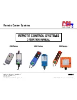
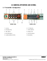
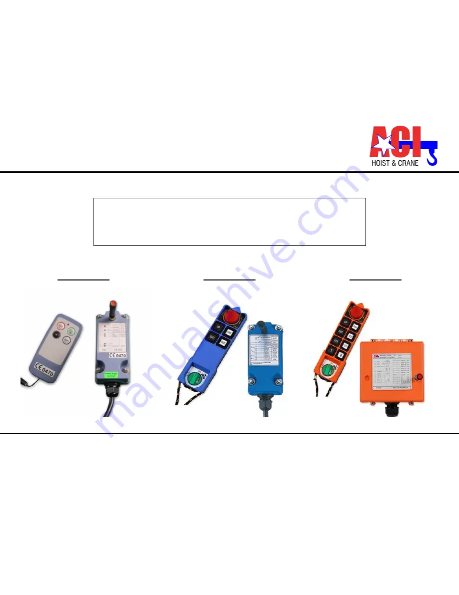
200 Series
400 Series
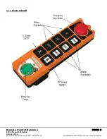
500 Series
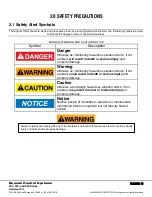
REMOTE CONTROL SYSTEMS
OPERATION MANUAL