


22
Chapter 2
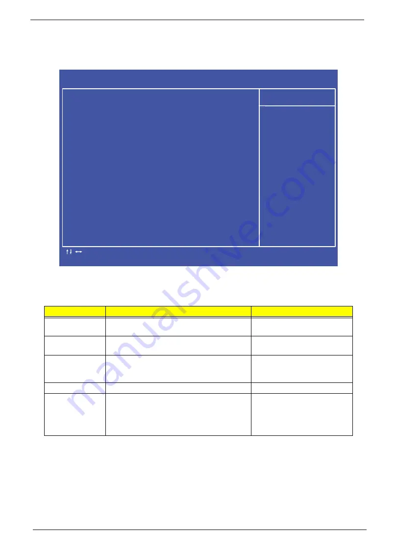
Standard CMOS Features
The Standard CMOS Features screen allows the user to set the system time and date as well as set HDD and
ODD options.
NOTE:
The screen above is for your reference only. Actual values may differ.
The table below describes the parameters in this screen. Settings in
boldface
are the default parameter
settings.
Parameter
Description
Format/Option
System Date
Sets the system date.
Format MM/DD/YYYY (month/
day/year)
System Time
Sets the system time. The hours are displayed
with 24-hour format.
Format: HH:MM:SS
(hour:minute:second)
SATA Port 1
Sets the disk type for SATA Port 1
Enter the Port 1 screen to
Enable
or DisableS.M.A.R.T.
for the HDD
SATA Port 2
Sets the disk type for SATA Port 2
Enter the Port 2 screen
Halt On
Instructs the BIOS to halt during boot up for
the selected error parameter.
Options:
•
All Errors
•
No Errors
•
All, But keyboard
C M O S S e t u p U t i l i t y - C o p y r i g h t ( C ) 1 9 8 5 - 2 0 0 5 , A m e r i c a n M e g a t r e n d s I n c .
S t a n d a r d C M O S F e a t u r e s
- / + / : V a l u e
H e l p I t e m
: M o v e
F 7 : P r e v i o u s V a l u e s
E n t e r : S e l e c t
F 8 : F a i l - S a f e D e f a u l t s
F 1 0 : S a v e
E S C : E x i t
F 9 : O p t i m i z e d D e f a u l
F 1 : G e n e r a l H e l p
S y s t e m D a t e [ T u e 8 / 2 5 / 2 0 0 9 ]
S y s t e m T i m e [ 0 5 : 0 0 : 3 3 ]
S A T A P o r t 1
[ H i t a c h i : H T 7 2 1 0 3 2 1 S ]
S A T A P o r t 2
[ S l i m t y p e D V D A D S 8 ]
H a l t O n [ A l l , B u t K e y b o a r d ]
X
X
U s e [ E n t e r ] , [ T A B ]
o r [ S h i f t - T A B ] t o
s e l e c t a f i e l d .
U s e [ + ] o r [ - ] t o
c o n f i g u r e s y s t e m D a t e
Содержание ZX4830 Series
Страница 6: ...VI Laptopblue...
Страница 10: ...X Table of Contents Laptopblue...
Страница 47: ...Chapter 2 37 Laptopblue...
Страница 53: ...43 Chapter 3 4 Lift the ODD bezel away 5 Close the ODD assembly Laptopblue...
Страница 57: ...47 Chapter 3 5 Forcefully pry the rear cover from the assembly i ii iii iv Laptopblue...
Страница 59: ...49 Chapter 3 4 Disconnect the audio cable from the audio board Laptopblue...
Страница 62: ...Chapter 3 52 7 Remove the HDD module from the bracket Laptopblue...
Страница 74: ...Chapter 3 64 15 Lift the mainboard shielding away from the chassis Laptopblue...
Страница 76: ...Chapter 3 66 4 Lift the WLAN module away Laptopblue...
Страница 78: ...Chapter 3 68 4 Lift the TV module away 5 Disconnect the other end of the TV cable and remove Laptopblue...
Страница 82: ...Chapter 3 72 4 Remove the fan Laptopblue...
Страница 87: ...77 Chapter 3 4 Remove the cables from the guide clips Laptopblue...
Страница 91: ...81 Chapter 3 8 Remove the LVDS cable 9 Remove the adhesive tape off the sensor cables Laptopblue...
Страница 97: ...87 Chapter 3 4 Lift the power board away from the bezel Laptopblue...
Страница 100: ...Chapter 3 90 4 Disconnect the webcam cable Laptopblue...
Страница 107: ...97 Chapter 3 3 Replace the speaker cable into the retention guides 4 Replace the speaker cable adhesive tape Laptopblue...
Страница 110: ...Chapter 3 100 Replacing the Webcam 1 Connect the webcam cable to the webcam board 2 Replace the webcam Laptopblue...
Страница 111: ...101 Chapter 3 3 Replace the two 2 screws Step Size Quantity Screw Type Webcam M2 3 2 Laptopblue...
Страница 115: ...105 Chapter 3 3 Replace the four 4 screws Step Size Quantity Screw Type LCD Panel M3 4 4 Laptopblue...
Страница 120: ...Chapter 3 110 12 Adhere the tape over the sensor cables and lay the cable through the retention hook Laptopblue...
Страница 121: ...111 Chapter 3 13 Connect the LVDS cable 14 Adhere the LVDC cable protective cover Laptopblue...
Страница 122: ...Chapter 3 112 15 Lay the LVDS cable through the retention guides and into the guide clip Laptopblue...
Страница 125: ...115 Chapter 3 3 Replace the two 2 screws Step Size Quantity Screw Type USB Board M2 5 4 2 Laptopblue...
Страница 128: ...Chapter 3 118 Replacing the Thermal Module 1 Replace the thermal module 2 Tighten the three 3 captive screws Laptopblue...
Страница 131: ...121 Chapter 3 Replacing the DIMM Module 1 Replace the DIMM Module 2 Press down to lock into place Laptopblue...
Страница 134: ...Chapter 3 124 3 Replace the two 2 connectors The gray cable is placed closest to the fan Laptopblue...
Страница 138: ...Chapter 3 128 4 Connect the left and right touchscreen sensor cable connectors Laptopblue...
Страница 140: ...Chapter 3 130 4 Adhere the inverter cable tape 5 Connect the webcam cable 6 Connect the LVDS cable Laptopblue...
Страница 143: ...133 Chapter 3 4 Connect the two 2 LCD to inverter board cables 1 and 2 1 2 Laptopblue...
Страница 146: ...Chapter 3 136 7 Replace the two 2 screws Step Size Quantity Screw Type ODD Module M2 5 4 2 Laptopblue...
Страница 151: ...141 Chapter 3 4 Replace 4 four screws Step Size Quantity Screw Type Rear Cover M2 5 7 4 Laptopblue...
Страница 155: ...145 Chapter 3 4 Close the ODD Laptopblue...
Страница 193: ...183 Appendix B Laptopblue...
Страница 196: ...186 Laptopblue...
Страница 197: ...187 Laptopblue...
Страница 198: ...188 Laptopblue...


