background image

BIOS Setup

24 - English

A26361-K522-Z122-3-7419

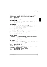
Fast Boot

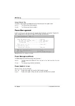
Fast Boot

can reduce the extent of the self-test and thus accelerate the system startup.

Auto

The fast self test is performed.

Disabled

When the device is switched on, the complete device configuration is tested.

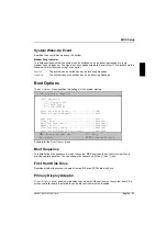
Silent Boot

With

Silent Boot

you can display or hide the startup messages while the system is booting.

Enabled

Hides the startup messages. The screen remains blank while the system is booting.

Disabled

Displays the startup messages while the system is booting.

Num Lock After Boot

Num Lock After Boot

activates the Num Lock function after system startup.

Memory Test

Enabled

The memory test is performed during the self test.

Disabled

The memory test is skipped.

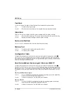
Configuration Table

To display this parameter you must enter the main menu and switch to Advanced level with

[F8]

[F8]

[F8]

[F8]

.

The

Configuration Table

parameter allows you to enable or disable the display of the configuration

table after the self test but before booting. The configuration table gives a summary of the hardware
devices and settings that BIOS detected.

Boot from LANDesk Service Agent / Boot over BOOTP

To display this parameter you must enter the main menu and switch to Advanced level with

[F8]

[F8]

[F8]

[F8]

.

The

Boot from LANDesk Service Agent / Boot over BOOTP

parameter allows the operating system to be

loaded from a server. This function is used particularly when neither floppy disk nor hard disk drives
are installed, or they have been switched off. Here there are two different boot protocols:

BootP

and

LSA

.

Boot from LANDesk Service Agent

Enabled

The

LSA

LAN-BIOS is activated and enables the operating system to be loaded from

a server via a local network connection with

LSA

.

Disabled

LAN boot is not possible. The LAN-BIOS is not activated.

Boot over BOOTP

Enabled

The

BootP

LAN-BIOS is activated and enables the operating system to be loaded

from a server via a local network connection with

BootP

.

Disabled

LAN boot is not possible. The LAN-BIOS is not activated.

Содержание V66LT

Страница 1: ...Systembaugruppe D1153 bis 500 MHz System board D1153 up to 500 MHz Technisches Handbuch Technical Manual ...

Страница 2: ......

Страница 3: ......

Страница 4: ...e è stato stampato su carta da riciclaggio Denna handbok är tryckt på recyclingpapper Dit handboek werd op recycling papier gedrukt Bestell Nr Order No A26361 K522 Z122 1 7419 A26361 K522 Z122 1 7419 A26361 K522 Z122 1 7419 A26361 K522 Z122 1 7419 Printed in the Federal Republic of Germany AG 0100 01 00 A26361 K522 Z122 1 7419 Systembaugruppe D1153 System board D1153 Technisches Handbuch Technical...

Страница 5: ...Systembaugruppe D1153 bis 500 MHz System board D1153 up to 500 MHz Technisches Handbuch Technical Manual Deutsch English Ausgabe Januar 2000 January 2000 edition ...

Страница 6: ... für den Fall der Patenterteilung oder GM Eintragung Liefermöglichkeiten und technische Änderungen vorbehalten Intel and Pentium are registered trademarks of Intel Corporation US Microsoft MS MS DOS Windows and Windows NT are Trademarks of Microsoft Corporation PS 2 and OS 2 Warp are registered trademarks of International Business Machines Inc All other trademarks referenced are trademarks or regi...

Страница 7: ...skettes Drives 18 IDE Primary Secondary 18 Onboard Peripherals 20 Onboard Device Settings 21 Power Management 22 Power Management Mode 22 Power Switch 4 sec 22 System Wake Up Event 23 Boot Options 23 Boot Sequence 23 First Hard Disk Drive 23 Primary Display Adapter 23 Fast Boot 24 Silent Boot 24 Num Lock After Boot 24 Memory Test 24 Configuration Table 24 Boot from LANDesk Service Agent Boot over ...

Страница 8: ...Contents A26361 K522 Z122 3 7419 VGA Palette Snoop 30 Graphics Aperture Size 30 Plug Play OS 30 Reset Resource Assignments 31 Load Default Settings 31 Abort Settings Change 31 Exiting Setup 31 Index 33 ...

Страница 9: ...is provided in the readme files on hard disk or on the supplied drivers diskettes or on the Drivers Utility CD Notational conventions The meanings of the symbols and fonts used in this manual are as follows Pay particular attention to texts marked with this symbol Failure to observe this warning endangers your life destroys the system or may lead to loss of data i Supplementary information remarks...

Страница 10: ... observe the instructions in the section Replacing the lithium battery The shipped version of this board complies with the requirements of the EEC directive 89 336 EEC Electromagnetic compatibility Compliance was tested in a typical PC configuration When installing the board refer to the specific installation information in the Operating Manual or Technical Manual of the receiving device Connectin...

Страница 11: ... pins etc when you replace the system board or components on it for example memory modules or processors Never use sharp objects screwdrivers for leverage Boards with electrostatic sensitive devices ESD are identifiable by the label shown When you handle boards fitted with ESDs you must observe the following points under all circumstances You must always discharge yourself e g by touching a ground...

Страница 12: ...PU SMM System Management Mode STOP Clock Control APM and ACPI compliant BIOS ATA compliant energy saving function of the hard disk Chipset Intel 82371AB PIIX4 with PCI Enhanced Local Bus IDE PIO Mode 4 DMA Mode 2 1 high speed serial interface NS16C550 compatible UARTs with 16 byte FIFOs 1 parallel interface SPP EPP and ECP according to IEEE 1284 1 interface for a floppy disk drive Soundchip Crysta...

Страница 13: ...the system board 1 2 3 4 5 6 7 8 9 10 11 12 1 Switching Regulator 2 CLK Generator 3 Intel chipset 440BX 4 SGRAM 5 Screen controller ATI Rage LT Pro AGP 6 SMC 677 7 Hardware monitoring 8 Flash ROM 9 LAN Controller Intel 82558 10 Intel PIIX4 11 Battery 12 Soundchip Crystal 4235B ISA ...

Страница 14: ...r voice modem CN17 9 Switch block 2 10 Connector for LCD interface CN8 11 Monitor port CN7 12 Parallel interface CN9 13 USB port CN14 14 Serial interface 1 CN13 15 Mouse port CN19 16 Keyboard port CN23 17 LAN connector CN28 18 Connector for slot board 19 Connector for CD in CN25 20 Connector for power supply CN26 21 Connector for power supply JP9 22 Connector for IDE 2 CN18 23 Connector for IDE 1 ...

Страница 15: ... query switch 2 On Password query enabled Off Password query disabled Setting the clock ratio between processor core and bus Switches 3 4 5 6 Clock ratio switch 3 switch 4 switch 5 switch 6 3 5 on off off on 4 off on on on 4 5 off on off on 5 off off on on 5 5 off off off on Switch block 2 Settings and functions In the following paragraphs the settings and functions of the single switches of switc...

Страница 16: ...hen Bildschirmspeichers für die angegebenen Farbtiefen in Bits pro Pixel 8 bpp 16bpp 24 bpp 32bpp 640 x 480 60 2 MByte 2 MByte 2 MByte 2 MByte 640 x 480 72 2 MByte 2 MByte 2 MByte 2 MByte 640 x 480 75 2 MByte 2 MByte 2 MByte 2 MByte 640 x 480 90 2 MByte 2 MByte 2 MByte 2 MByte 640 x 480 100 2 MByte 2 MByte 2 MByte 2 MByte 800 x 600 60 2 MByte 2 MByte 2 MByte 4 MByte 800 x 600 70 2 MByte 2 MByte 2 ...

Страница 17: ...y modules must be designed for a clock frequency of 66 MHz or 100 MHz or higher meets PC100 specification Installing memory modules 2 2 Ê Flip the holders on each side of the relevant location outwards Ê Insert the memory module into the location 1 Ê At the same time flip the lateral holders upwards until the memory module snaps in place 2 If you use ECC memory modules in the Memory Cache Options ...

Страница 18: ...e centimeter Ê Lift the processor out of the slot Installing the Pentium II 2 1 Ê Insert Pentium II in the holder with the labeled side facing downwards so that a gap of about one centimeter remains between the contacts of the Pentium II and the processor socket 1 Ê Push the Pentium II in the holder until the clamps 2 to the left and right snap into place Ê Set the bus frequency of the new Pentium...

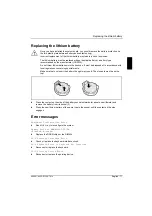
Страница 19: ...ncerning special waste Make sure that you insert the battery the right way round The plus pole must be on the top Ê Press the contact on the side of the battery socket outwards for about one millimeter and remove the battery from its socket 2 Ê Press the new lithium battery of the same type in the socket until the contact on the side engages Error messages Equipment Configuration Error Ê Run BIOS ...

Страница 20: ...onnections and BIOS Setup configuration Should the error persist replace the drive or the system board Hard Disk Drive s Write Protected Ê Call BIOS Setup and set the setting to Normal CPU Clock Mismatch Ê Call the BIOS Setup The message will automatically disappear Real Time Clock Error Ê Check the real time clock circuit or replace the real time clock CMOS Battery Bad Ê Replace the battery CMOS ...

Страница 21: ...nment for the onboard parallel port or disable it Onboard Serial Port Conflict s Ê In BIOS setup change the onboard serial port address in Setup or change the add on board serial port address Onboard Parallel Port Conflict s Ê In BIOS setup change the onboard parallel port address or set the parallel port address of the add on board to others Onboard xxx Conflict s Ê Try to reassign or disable on ...

Страница 22: ......

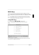
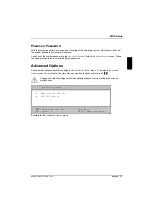
Страница 23: ...e the battery Some menu items may not be present on your system Calling BIOS Setup Ê To call BIOS Setup press Ctrl Ctrl Ctrl Ctrl Alt Alt Alt Alt Esc Esc Esc Esc during system startup i The following figures are examples and may be different on your system Setup Utility System Information Product Information Disk Drives Onboard Peripherals Power management Boot Options Date and Time System Securit...

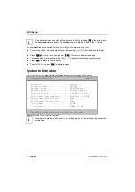
Страница 24: ...Press Esc Esc Esc Esc to return to the main menu Ê To exit BIOS Setup press Esc Esc Esc Esc in the main menu System Information The System Information menu displays the standard system functions of the device System Information Page 1 2 Processor Pentium II Processor Speed 400 MHz Internal Cache 32 KB Enabled External Cache 512 KB Enabled Diskette Drive A 1 44 MB 3 5 inch Diskette Drive B 1 44 MB ...

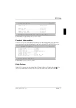
Страница 25: ...he device the serial numbers of device and system board as well as the system BIOS and DMI BIOS versions Product Information Page 1 1 Product Name SCOVERY System S N Serial Main Board ID 98134 1 Main Board S N 0000000000000000 System Board Version V3 2 SMBIOS Version V2 1 System BIOS ID R04 A1 M1 EN BIOS Release Date Dec 22 1998 Esc Back to Main Menu Example for the Product Information menu Disk D...

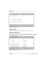
Страница 26: ... ç key IDE Primary Secondary In the IDE Primary Channel Master IDE Primary Channel Slave IDE Secondary Channel Master IDE Secondary Channel Slave submenus you can make the settings for the IDE drives The submenus are shown in Advanced level only IDE Primary Secondary Channel Master Slave Page 1 1 Type Auto Cylinder XXXX Head XXXX Sector XXXX Size XXXX MB Hard Disk Size 504MB Auto Hard Disk Block M...

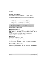
Страница 27: ...s function Advanced PIO Mode Programmed Input Output Mode Defines the transfer rate of the IDE hard disk drive To display this parameter you must enter the main menu and switch to Advanced level with F8 F8 F8 F8 Auto Automatically detects if this function is supported Disabled Does not support this function Hard Disk 32 bit Access This field determines if a 32 bit hard disk access is possible To d...

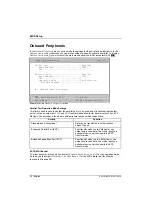
Страница 28: ...r the parallel port is to be used as a bi directional input output port or just as an output port ECP and EPP transfer modes allow faster transfer rates of 2 and 2 4 Mbytes s These modes will only work with peripheral devices which support them Setting Function Standard and Bi directional Data can be transferred in both directions across the port Enhanced Parallel Port EPP Fast transfer mode up to...

Страница 29: ...ontroller is disabled IDE controller This field allows you to enable and disable the onboard IDE controller Enabled The IDE controller is enabled Disabled The IDE controller is disabled PS 2 Mouse Controller This field is used to enable and disable the built in PS 2 mouse controller on the system board Enabled The PS 2 mouse controller is enabled Disabled The PS 2 mouse controller is disabled USB ...

Страница 30: ... Hard Disk Standby Timer Off Minute s System Sleep Timer 30 Minute s Sleep Mode Power Switch 4 Sec Power Off System Wake Up Event Modem Ring Indicator Enabled Move Highlight Bar F1 Help Esc Exit Change Setting Example for the Power Management menu Power Management Mode This field defines the extent of the energy saving functions Enabled The functions set in the fields IDE Hard Disk Standby Timer a...

Страница 31: ...loppy Disk 2nd Hard Disk 3rd IDE CD ROM First Hard Disk Drive IDE Primary Display Adapter Auto Fast Boot Auto Silent Boot Enabled Num Lock After Boot Enabled Memory Test Disabled Configuration Table Enabled Boot from LSA BootP boot server Disabled Move Highlight Bar F1 Help Esc Exit Change Setting Example for the Boot Options menu Boot Sequence This field defines the sequence in which the system B...

Страница 32: ...ble or disable the display of the configuration table after the self test but before booting The configuration table gives a summary of the hardware devices and settings that BIOS detected Boot from LANDesk Service Agent Boot over BOOTP To display this parameter you must enter the main menu and switch to Advanced level with F8 F8 F8 F8 The Boot from LANDesk Service Agent Boot over BOOTP parameter ...

Страница 33: ... ç keys System Security The System Security menu offers you various options for protecting your system and personal data from unauthorized access By combining these options you can achieve optimum protection for your system Setup Password The Setup Password menu allows you to install a setup password The setup password prevents unauthorized callup of the BIOS setup Setting the Setup password To se...

Страница 34: ...ll alphanumerical characters can be used no differentiation is made between upper case and lower case Passwords are not displayed as they are entered Ê Re enter the password in the Enter Password again field and press the Enter key Ê Confirm the Set or Change Password line with the Enter key to save the password Ê Press Esc Esc Esc Esc to enter the System Security menu The Setup Password entry is ...

Страница 35: ...low the same procedure as in setting the Setup password Advanced Options You can make advanced system settings in the Advanced Options menu To display the Advanced Options menu you must enter the main menu and switch to Advanced level with F8 F8 F8 F8 Change the default settings only for special applications Incorrect settings can cause malfunctions Advanced Options Memory Cache Options PnP PCI Op...

Страница 36: ... which parts of the main memory and BIOS can be temporarily copied The system performance is higher when the cache is switched on You must disable the cache if the access time is too short for older applications Select Enabled if you want to switch on the internal cache External Cache This field switches the external cache on and off Select Enabled if you want to switch on the external cache Cache...

Страница 37: ...orruption is corrected no error message An error message is issued for two or more bit corruption s Use this setting for all ECC memory modules PnP PCI Options Calls the submenu in which you can make the settings for Plug Play and the PCI bus PnP PCI Options Page 1 1 PCI IRQ Setting Auto INTA INTB INTC INTD PCI Slot 1 PCI Slot 2 PCI IRQ Sharing Yes VGA Palette Snoop Disabled Graphics Aperture Size...

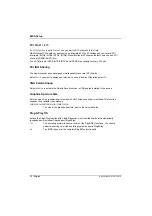
Страница 38: ...o several boards Otherwise select No VGA Palette Snoop Select Enabled to activate the Palette Snoop function in VGA boards installed in the device Graphics Aperture Size Sets the size of the graphics aperture when an AGP screen controller is installed This function expands the available video memory 4MB 8MB 16MB 32MB 64MB 128MB 256MB The size of the graphics aperture is set to the selected value P...

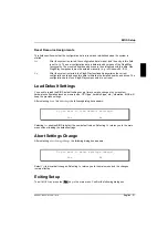
Страница 39: ... data of non Plug Play components are not reset Load Default Settings You need to reload the BIOS default settings every time you make changes to your system hardware configuration such as memory size CPU type hard disk type etc otherwise BIOS will keep the previous settings After selecting Load Default Settings the following dialog box appears Do you want to load default settings Yes No Selecting...

Страница 40: ......

Страница 41: ...ration 27 calling 15 exiting 31 loading defaults 31 Main menu 15 Standard shell 15 Boot from LANDesk Service Agent 24 Boot Options 23 Boot over BOOTP 24 Boot Sequence 23 C Cache 28 Configuration Table 24 Connector 6 D Date and Time 25 Disk Drives 18 E Energy saving functions 22 Enter setup 15 Error messages 11 Exiting Setup 31 External cache 28 F Fast boot 24 First Hard Disk Drive 23 Floppy Drives...

Страница 42: ...ng 9 removing 9 Memory test 24 Monitor controller 23 Multifunctional PCI boards 30 N Notational conventions 1 Num Lock After Boot 24 O Onboard controller 21 Onboard Device Settings 21 Onboard Peripherals 20 Operating system boot sequence 23 loading from server 24 P PCI 29 PCI IRQ Setting 29 PCI IRQ Sharing 30 PCI Slot 1 2 30 Pentium II installing 10 removing 10 setting bus frequency 7 Plug Play 29...

Страница 43: ... Reset Resource Assignments 31 S Screen resolutions 8 Security functions 25 Self test reduced 24 Setting bus frequency 7 Setting date 25 Setting display 7 Setting floppy disk drive 18 Setting the clock ratio 7 Setting time 25 Setup password 25 Skipping password query 7 Switch blocks 6 System information 16 System password 27 System Security 25 System start 23 System Wake Up Event 23 V VGA Palette ...

Отзывы: