background image

DV420 /DV460 /DV550

17

2.  Press [ ] or [ ] button to toggle among the {

YEAR

}, 

{

MONTH

}, {

DAY

}, {

HOUR

}, {

MINUTE

}, and {

DAYLIGHT 

SAVING TIME

} settings.

3.  Press [ ] or [ ] button to adjust all settings except 

{

DAYLIGHT SAVING TIME

}. 

CONFIGURATION1 RESET

Reset all settings in the 

CONFIGURATION1

 menu to factory 

preset values.

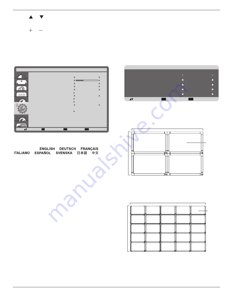
4.2.6.  CONFIGURATION2 menu

PIP

1
2

3

SET

EXIT

MENU

2

:SEL

:NEXT

LANGUAGE

OSD TURN OFF

OSD H POSITION

OSD V POSITION

MONITOR ID

IR CONTROL

TILING

POWER ON DELAY

CLOSED CAPTION

CONFIGURATION2 RESET

INFORMATION OSD

MONITOR INFORMATION

CONFIGURATION2

:RETURN

:EXIT MENU

OFF

OFF

50

50

3 SEC.

1

45

LANGUAGE

Select the language used in the OSD menu.
The options are: {

} / {

} / {

} / 

{

} / {

} / {

} / {

} / {

}.

OSD TURN OFF

Set the period of time the OSD menu stays on the screen.
The options are: {

5 ~ 120

} seconds.

OSD H POSITION

Adjust the horizontal position of the OSD menu.

OSD V POSITION

Adjust the vertical position of the OSD menu.

INFORMATION OSD

Set the period of time the information OSD displayed on the 

upper right corner of the screen. The information OSD will 

display when input signal is changed.
The information OSD will remain on the screen with {

OFF

selection.
The options are: {

OFF, 3 SEC. ~ 10 SEC.

}.

MONITOR INFORMATION

Displays the information about your display, including 

MODEL 

NAME

 and 

SERIAL

.

MONITOR ID

Set the ID number for controlling the display via the RS232C 

connection. Each display must have a unique ID number when 

multiple sets of this display are connected.

IR CONTROL

Select the operation mode of the remote control unit when 

multiple displays are connected via the RS232C connection.

• 

{

NORMAL

} - All displays can be operated normally by the 

remote control.

• 

{

LOCK

} - Lock the remote control function of this display. To 

unlock, press and hold the [

DISPLAY

] button on the remote 

control for 5 (five) seconds.

TILING

With this function you can create a single large-screen matrix 

(video wall) that consists of up to 

150

 sets of this display (

up to 

15-set at the horizontal and 10 set at the vertical side

). This 

function requires a daisy-chain connection.

EXIT

MENU

:SEL

+-:ADJ

:RETURN

:EXIT MENU

TILING

H MONITORS

V MONITORS

POSITION

FRAME COMP.

ENABLE

1

1

1

OFF

OFF

Example: 2 x 2 screen matrix (4 displays)

H MONITORS = 2 displays 

V MONITORS = 2 displays

1

2

3

4

H MONITORS

MONIT

ORS

Position

Example: 5 x 5 screen matrix (25 displays)

H MONITORS = 5 displays 

V MONITORS = 5 displays

1

2

6

7

3

4

8

9

5

10

11

12

13

14

15

16

17

18

19

20

21

22

23

24

25

H MONITORS

V MONIT

ORS

Position

•  H MONITORS

 - Select the number of displays on the 

horizontal side.

•  V MONITORS

 - Select the number of displays on the vertical 

side.

Содержание DV420

Страница 1: ...DV420 DV460 DV550 User Manual English...

Страница 2: ...he apparatus and be easily accessible Read and follow these instructions when connecting and using your Display Unplug the display if you are not going to use it for an extensive period of time Unplug...

Страница 3: ...erence when the equipment is operated in a commercial environment This equipment generates uses and can radiate radio frequency energy and if not installed and used in accordance with the instructions...

Страница 4: ...ith all applicable legal requirements and to stay well within the EMF standards applicable at the time of producing the products 3 We are committed to develop produce and market products that cause no...

Страница 5: ...nformation on recycling contact www eia org Consumer Education Initiative Waste Electrical and Electronie Equipment WEEE Attention users in European Union private households This marking on the produc...

Страница 6: ...product must not be disposed of with your other household waste Instead it is your responsibility to dispose of your waste equipment by handing it over to a designated collection point for the recycl...

Страница 7: ...g and Removing Table Stands optional 2 1 5 Mounting on a Wall 3 1 5 1 VESA Grid 3 2 Parts and Functions 4 2 1 Control Panel 4 2 2 Input Output Terminals 5 2 3 Remote Control 6 2 3 1 General functions...

Страница 8: ...Video Signal Cable D SUB to D SUB Cable Power switch cover and screw M3x8 x1 NOTES For all other regions apply a power cord that conforms to the AC voltage of the power socket and has been approved b...

Страница 9: ...ng the stand in the guide block tighten the screws on both sides of the display NOTE The longer side of the stand should face the front of the display Carrying handle Thumbscrews Longer portions face...

Страница 10: ...anty does not cover damage caused by improper installation 4 For the wall mounting kit use M6 mounting screws having a length 10 mm longer than the thickness of the mounting bracket and tighten them s...

Страница 11: ...own to adjust the selected item while OSD menu is on 8 MENU button Return to previous menu while OSD menu is on or to activate the OSD menu when OSD menu is off NOTE Keyboard Control Lock Mode This fu...

Страница 12: ...MI IN HDMI video audio input 7 DisplayPort DisplayPort video input 8 DVI IN DVI D video input 9 DVI OUT VGA OUT DVI or VGA video output 10 VGA IN D Sub VGA video input 11 VGA AUDIO IN Audio input for...

Страница 13: ...side the OSD menu 8 AUTO ADJUST button Press to run the Auto Adjust function NOTE This button is functional for VGA input only 9 MUTE button Press to turn the mute function on off 10 VIDEO SOURCE butt...

Страница 14: ...do not intend to use the remote control for a long period remove the batteries 2 3 3 Handling the remote control Do not subject to strong shock Do not allow water or other liquid to splash the remote...

Страница 15: ...Switch Cover A cover for the power switch is provided to prevent the display from being turned on or off accidentally To lock the cover into position 1 Align and insert the cover to the indentation l...

Страница 16: ...0 9 3 2 Connecting External Equipment DVD VCR VCD 3 2 1 Using COMPONENT video input DVD VCR VCD AUDIO IN COMPONENT IN YPbPr COMPONENT Out YPbPr Audio Out R L 3 2 2 Using HDMI video input DVD VCR VCD H...

Страница 17: ...Connecting a PC 3 3 1 Using VGA input PC VGA IN VGA AUDIO IN VGA Out D Sub 15 pin Audio Out AUDIO IN R L 3 3 2 Using DVI input PC VGA AUDIO IN DVI Out Audio Out AUDIO IN R L DVI IN 3 3 3 Using HDMI i...

Страница 18: ...DV420 DV460 DV550 11 3 4 Connecting Audio Equipment 3 4 1 Connecting external speakers External speakers 3 4 2 Connecting an external audio device Stereo Amplifier AUDIO OUT R L Audio In...

Страница 19: ...ection Connect the RS232C OUT connector of DISPLAY 1 to the RS232C IN connector of DISPLAY 2 PC DISPLAY 1 DISPLAY 2 RS 232C IN RS 232C RS 232C OUT RS 232C IN 3 5 2 Digital video connection Connect the...

Страница 20: ...EXIT MENU SEL NEXT BRIGHTNESS CONTRAST SHARPNESS BLACK LEVEL TINT COLOR COLOR TEMPERATURE USER COLOR GAMMA SELECTION NATIVE NATIVE NOISE REDUCTION FILM MODE PICTURE RESET PICTURE RETURN EXIT MENU 50 5...

Страница 21: ...ected OFF Once a signal is connected it can only be selected manually H POSITION Press the button to move the image to the right or to move the image to the left V POSITION Press the button to move th...

Страница 22: ...cture PIP H POSITION Adjust the horizontal placement of the sub picture PIP V POSITION Adjust the vertical placement of the sub picture SUB INPUT Select the input signal for the sub picture PIP RESET...

Страница 23: ...et the hour and minute for the display to turn on 2 POWER OFF schedule Press or button to set the hour and minute for the display to turn off Select or leave an empty __ for both the hour and minute s...

Страница 24: ...s the information about your display including MODEL NAME and SERIAL MONITOR ID Set the ID number for controlling the display via the RS232C connection Each display must have a unique ID number when m...

Страница 25: ...displayed without sync TT1 TT2 TT3 TT4 Four types of information not related to the displayed images are displayed For example news and weather forecast NOTE Check with each supplier of your video sof...

Страница 26: ...The selection QUICK may cause a slight noise TERMINAL SETTING Select the mode to display the HDMI or DVI signal according to their signal format depending on their source device DVI MODE Used for DVI...

Страница 27: ...mask and Default gateway automatically If disabled you will be prompted to enter the following value manually Finally press SET button to store and save the chosen values ADVANCED OPTION RESET Reset...

Страница 28: ...50 Hz 27 MHz HDTV Resolution Standard Resolution Active Resolution Refresh Rate Pixel Rate Aspect Ratio Stand for Mode H Pixels V Lines 720p 1280 720 50 Hz 74 25 MHz 16 9 Normally DVB Mode 60 Hz 1080i...

Страница 29: ...ft lint free cloth If the surface becomes dirty soak a soft lint free cloth in a mild detergent solution Wring the cloth to remove excess liquid Wipe the surface of the display to remove dirt Then use...

Страница 30: ...zoom mode is not correctly set Use the Zoom mode or Custom zoom function in the Screen menu to fine tune display geometry and time frequency parameter Can hear sound but no picture Improperly connect...

Страница 31: ...ideo 720p 1080p 1920 x 1080 60 Hz WUXGA Audio 48 KHz 2 Channel L R Supports LPCM only DVI D Input DVI D jack Digital RGB TMDS Video VGA Input D Sub Jack x 1 15 pin Analog RGB 0 7V p p 75 H CS V TTL 2...

Страница 32: ...mperature Operational 5 40 C Landscape 5 35 C Portrait Storage 20 60 C Humidity Operational 20 80 RH No condensation Storage 10 90 RH No condensation Altitude Operational 0 3 000 m Storage Shipment 0...

Страница 33: ...48 KHz 2 Channel L R Supports LPCM only DVI D Input DVI D jack Digital RGB TMDS Video VGA Input D Sub Jack x 1 15 pin Analog RGB 0 7V p p 75 H CS V TTL 2 2k SOG 1V p p 75 MAX 720p 1080p 1920 x 1080 6...

Страница 34: ...ational 5 40 C Landscape 5 35 C Portrait Storage 20 60 C Humidity Operational 20 80 RH No condensation Storage 10 95 RH No condensation Altitude Operational 0 3 000 m Internal Speaker Item Specificati...

Страница 35: ...io 48 KHz 2 Channel L R Supports LPCM only DVI D Input DVI D jack Digital RGB TMDS Video VGA Input D Sub Jack x 1 15 pin Analog RGB 0 7V p p 75 H CS V TTL 2 2k SOG 1V p p 75 MAX 720p 1080p 1920 x 1080...

Страница 36: ...mperature Operational 5 40 C Storage 20 60 C Humidity Operational 20 80 RH No condensation Storage 5 95 RH No condensation Altitude Operational 0 3 000 m Internal Speaker Item Specifications Type 1 Wa...

Страница 37: ...2014 All rights reserved Specifications are subject to change without notice...

Отзывы: