System Utilities
2-9
2. Type a new password in the
Enter New Password
field. Passwords are not case
sensitive and the length must not exceed 12 alphanumeric characters (A-Z, a-z, 0-9).
Retype the password in the
Confirm New Password
field.
IMPORTANT
:
+
Use care when typing a password. Characters do not appear on the
screen.
3. Press
Enter
.
After setting the password, the computer sets the
User Password
parameter to
Set
.
NOTE:
NOTE
:
Password on Boot
must be set to
Enabled
to activate password feature.
4. Press
F10
to save changes and exit
BIOS Setup Utility
.
Removing a Password
0
Perform the following:
1. Use the
↑
and
↓
keys to highlight
Set Supervisor Password
and press
Enter
. The
Set Supervisor Password
dialog box appears:
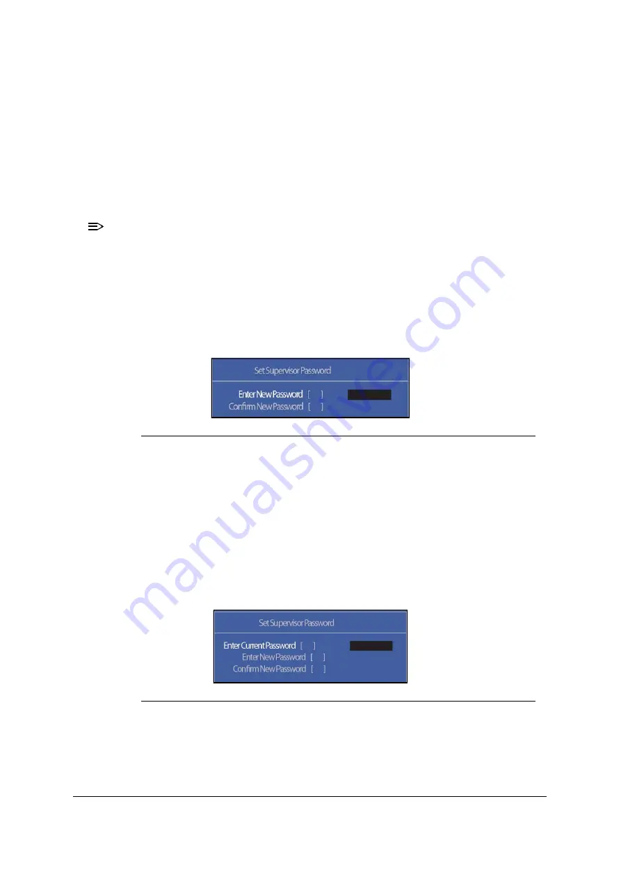
Figure 2-5. Set Supervisor Password
2. Type current password in
Enter Current Password
field and press
Enter
.
3. Press
Enter
twice without typing anything in
Enter New Password
and
Confirm
New Password
fields. Computer will set
Supervisor Password
parameter to
Clear
.
4. Press
F10
to save changes and exit the
BIOS Setup Utility
.
Changing a Password
0
1. Use the
↑
and
↓
keys to highlight
Set Supervisor Password
and press
Enter
. The
Set Supervisor Password
dialog box appears.
Figure 2-6. Set Supervisor Password
2. Type current password in
Enter Current Password
field and press
Enter
.
3. Type new password in
Enter New Password
field. Retype new password in
Confirm New Password
field.
4. Press
Enter
. Computer sets
Supervisor Password
parameter to
Set
.
Содержание Aspire V5-573
Страница 1: ...Aspire V7 582 V5 573 SERVICE GUIDE ...
Страница 11: ...CHAPTER 1 Hardware Specifications ...
Страница 14: ...1 4 ...
Страница 58: ...1 48 Hardware Specifications and Configurations ...
Страница 59: ...CHAPTER 2 System Utilities ...
Страница 76: ...2 18 System Utilities Figure 2 20 No AC Power Detected 1 or 2 Figure 2 21 No AC Power Detected 2 of 2 ...
Страница 110: ...2 52 System Utilities ...
Страница 111: ...CHAPTER 3 Machine Maintenance Procedures ...
Страница 114: ...3 4 ...
Страница 123: ...Machine Maintenance Procedures 3 13 ID Size Torque Quantity Screw Type Red Call out M2 5 6 I 2 4 0 2KGF CM 17 ...
Страница 127: ...Machine Maintenance Procedures 3 17 4 Remove HDD cable from HDD connector C Figure 3 9 Figure 3 9 HDD Cable C ...
Страница 133: ...Machine Maintenance Procedures 3 23 ID Size Torque Quantity Screw Type C M2 5 3I 2 0 0 2KGF CM 1 ...
Страница 142: ...3 32 Machine Maintenance Procedures ID Size Torque Quantity Screw Type A M2 5 3 0 I 1 8 0 2KGF CM 6 ...
Страница 144: ...3 34 Machine Maintenance Procedures ID Size Torque Quantity Screw Type B M2 0 4 2 0 1 8 0 2KGF CM 1 ...
Страница 148: ...3 38 Machine Maintenance Procedures ID Size Torque Quantity Screw Type D M2 5 3I 2 0 0 2KGF CM 1 ...
Страница 180: ...3 70 Machine Maintenance Procedures ID Size Torque Quantity Screw Type D M2 5 3I 2 0 0 2KGF CM 1 ...
Страница 184: ...3 74 Machine Maintenance Procedures ID Size Torque Quantity Screw Type B M2 0 4 2 0 1 8 0 2KGF CM 1 ...
Страница 186: ...3 76 Machine Maintenance Procedures ID Size Torque Quantity Screw Type A M2 5 3 0 I 1 8 0 2KGF CM 6 ...
Страница 199: ...Machine Maintenance Procedures 3 89 Figure 3 109 Connecting HDD B ...
Страница 201: ...Machine Maintenance Procedures 3 91 ID Size Torque Quantity Screw Type C M2 5 3 0 I 1 8 0 2KGF CM 1 ...
Страница 203: ...Machine Maintenance Procedures 3 93 ID Size Torque Quantity Screw Type Red Call out M2 5 6 I 2 4 0 2KGF CM 17 ...
Страница 205: ...CHAPTER 4 Troubleshooting ...
Страница 229: ...CHAPTER 5 Jumper and Connector Locations ...
Страница 238: ...5 10 Jumper and Connector Locations ...
Страница 239: ...CHAPTER 6 FRU Field Replaceable Unit List ...
Страница 240: ...6 2 Exploded Diagrams 6 4 FRU List 6 7 Screw List 6 46 ...
Страница 242: ...6 4 FRU Field Replaceable Unit List Exploded Diagrams 0 Figure 6 1 System Exploded Diagram 1 2 3 4 5 6 7 8 10 9 12 11 ...
Страница 285: ...CHAPTER 7 Model Definition and Configuration ...
Страница 286: ...7 2 Acer Aspire V7 582 7 3 Acer Aspire V5 573 7 28 ...
Страница 360: ...7 76 Model Definition and Configuration ...
Страница 361: ...CHAPTER 8 Test Compatible Components ...
Страница 362: ...8 2 Microsoft Windows 8 Environment Test 8 4 ...
Страница 372: ...8 12 Test Compatible Components ...
Страница 373: ...CHAPTER 9 Online Support Information ...
Страница 374: ...9 2 Introduction 9 3 ...
Страница 376: ...9 4 Online Support Information ...


