Troubleshooting
4-11
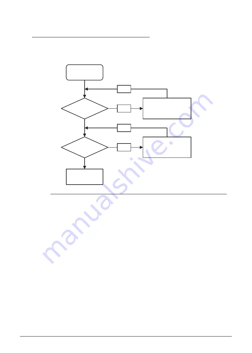
Internal Speaker Failure
0
If internal Speakers fail, perform the following, one at a time. Do not replace a non-defective
FRU:
Figure 4-6.
Internal Speaker Failure
Sound Problems
0
Perform the following, one at a time.
1. Boot the computer.
2. Navigate to Start
Control Panel
System and Maintenance
System
Device
Manager. Check the Device Manager to determine that:
The device is properly installed
There are no red Xs or yellow exclamation marks
There are no device conflicts
No hardware is listed under Other Devices
3. If updated recently, roll back the audio driver to the previous version.
4. Remove and reinstall the audio driver.
5. Make sure that all volume controls are set mid range:
Click the volume icon on the task bar
Drag the slider to 50. Confirm that the volume is not muted.
Click Mixer to verify that other audio applications are set to 50 and not muted.
Start
Is speaker cable
well connected?
Is speaker
OK?
Replace M/B
Reconnect the
speaker cable
OK
NG
Replace speaker
OK
NG
Содержание Aspire 5560
Страница 1: ... Aspire 5560 SERVICEGUIDE ...
Страница 10: ...6 ...
Страница 11: ...CHAPTER 1 Hardware Specifications ...
Страница 14: ...1 4 ...
Страница 34: ...1 24 Hardware Specifications and Configurations System Block Diagram Figure 1 12 System Block Diagram ...
Страница 52: ...1 42 Hardware Specifications and Configurations ...
Страница 53: ...CHAPTER 2 System Utilities ...
Страница 69: ...CHAPTER 3 Machine Maintenance ...
Страница 72: ...3 4 ...
Страница 81: ...Machine Maintenance 13 5 Pry the ODD bezel off the module Figure 3 10 ODD Bezel ...
Страница 86: ...18 Machine Maintenance 4 Remove the WLAN module from the slot Figure 3 18 WLAN Module ...
Страница 97: ...Machine Maintenance 29 4 Lift the speakers from the upper cover Figure 3 38 Speaker Screws ...
Страница 107: ...Machine Maintenance 39 4 Remove the thermal module from the mainboard Figure 3 54 Thermal Module ...
Страница 112: ...44 Machine Maintenance 6 Remove the LCD module from the lower case Figure 3 62 LCD Module ...
Страница 131: ...Machine Maintenance 63 3 Secure the bezel with the two screw covers Figure 3 93 LCD Bezel Screw Covers ...
Страница 134: ...66 Machine Maintenance 5 Position the DC input cable on the lower case Figure 3 98 DC Input Cable ...
Страница 167: ...CHAPTER 4 Troubleshooting ...
Страница 198: ...4 32 Troubleshooting ...
Страница 199: ...CHAPTER 5 Jumper and Connector Locations ...
Страница 205: ...CHAPTER 6 FRU List ...
Страница 206: ...6 2 Aspire 5560 Exploded Diagrams 6 4 Main Assembly 6 4 LCD Assembly 6 5 FRU List 6 7 ...
Страница 220: ...6 16 FRU Field Replaceable Unit List ...
Страница 221: ...CHAPTER 7 Model Definition and Configuration ...
Страница 222: ...7 2 Aspire 5560 7 3 ...
Страница 223: ...Model Definition and Configuration 7 3 Model Definition and Configuration Aspire 5560 0 ...
Страница 224: ...7 4 Model Definition and Configuration ...
Страница 225: ...CHAPTER 8 Test Compatible Components ...
Страница 226: ...8 2 Microsoft Windows 7 Environment Test 8 4 ...
Страница 236: ...8 12 Test Compatible Components ...
Страница 237: ...CHAPTER 9 Online Support Information ...
Страница 238: ...9 2 ...
Страница 240: ...9 4 Online Support Information ...


