


8
Chapter 1
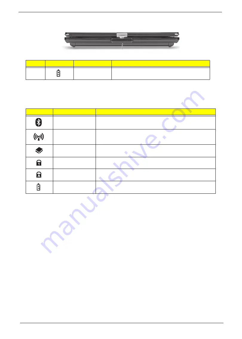
Rear View
Indicators
The computer has several easy-to-read status indicators. The battery indicator is visible even when the
computer cover is closed.
NOTE:
1.
Charging:
The battery light shows amber when the battery is charging. 2.
Fully charged:
The light
shows green when in AC mode.
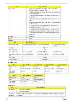
No.
Icon
Item
Description
1
Battery bay
Houses the computer's battery pack.
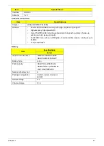
Icon
Function
Description
Bluetooth
Indicates the status of Bluetooth communication.
Wireless LAN
Indicates the status of Wireless LAN/3G communication.
HDD
Indicates when the hard disk drive is active.
Num Lock
Lights up when Num Lock is activated.
Caps Lock
Lights up when Caps Lock is activated.
Battery
Indicates the computer's battery status.
1
Содержание Aspire 1420P Series
Страница 6: ...vi...
Страница 10: ...x Table of Contents...
Страница 13: ...Chapter 1 3 System Block Diagram...
Страница 32: ...22 Chapter 1...
Страница 48: ...38 Chapter 2...
Страница 60: ...50 Chapter 3 4 Remove the one 1 screw 5 Remove the 3G module Step Screw Quantity Screw Type 3G Module M2 3 1...
Страница 64: ...54 Chapter 3 4 Unlock the FPC 5 Remove the FPC and keyboard...
Страница 66: ...56 Chapter 3 4 Remove the hinge cap 5 Remove the hinge bezel...
Страница 70: ...60 Chapter 3 10 Pull the upper cover away...
Страница 80: ...70 Chapter 3 6 Remove the two 2 screws 7 Remove the LED board Step Screw Quantity Screw Type LED Board M2 4 2...
Страница 85: ...Chapter 3 75 11 Lift up the main board from the inside edge and pull away 12 Remove the CRT cable...
Страница 94: ...84 Chapter 3 7 Pry up the bezel top edge and remove...
Страница 100: ...90 Chapter 3 6 Pull up the LCD cable from the adhesive 7 Pull the touchscreen cable from the adhesive...
Страница 105: ...Chapter 3 95 6 Remove the antenna cable from the retention guide hooks 7 Peel the antenna foil off the cover...
Страница 119: ...Chapter 3 109 7 Insert the stylus...
Страница 127: ...Chapter 3 117 7 Connect the touchscreen cable Replacing the CRT Board 1 Connect the CRT cable 2 Turn the CRT board over...
Страница 134: ...124 Chapter 3 6 Lock the main board connector 7 Replace the I O cable in the IO board 8 Lock the I O board connector...
Страница 142: ...132 Chapter 3 2 Replace the hinge cap 3 Replace the three 3 screws Step Screw Quantity Screw Type Hinge Covers M2 3 3...
Страница 144: ...134 Chapter 3 4 Press down the keyboard top edge Replacing the 3G Module 1 Replace the 3G module...
Страница 148: ...138 Chapter 3 2 Replace the HDD in the bay 3 Adhere the black tape 4 Replace the HDD FPC...
Страница 149: ...Chapter 3 139 5 Lock the HDD FPC Replacing the Module Cover 1 Insert the side of the module cover into the slots...
Страница 150: ...140 Chapter 3 2 Replace the module pressing firmly around the edges 3 Tighten the six 6 captive screws...
Страница 152: ...142 Chapter 3 3 Lock the battery Replacing the Dummy Card 1 Insert the dummy card into the slot...
Страница 202: ...192 Appendix A...
Страница 212: ...202...
Страница 215: ...205...
Страница 216: ...206...


