Chapter 3
67
Disassembling the External Modules
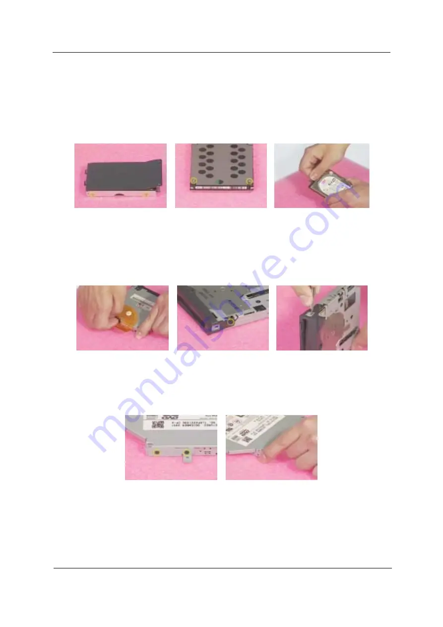
Disassembling the HDD Module
1.
Remove the four (two on each side) screws on HDD carrier. Then you can take out the HDD drive from
the carrier.
2.
Turn out the two screws holding the HDD EMI plate then remove it.
3.
Disconnect the hard disk drive connector.
Disassembling the Floppy Disk Drive Module
1.
Release the kapton that fastens the FDD FPC, then disconnect the floppy disk drive FFC.
2.
Unscrew the two screw holding the FDD door. One on each side.
3.
Use a tool (a tip of a pen or an uncurved paper clipper) to release the FDD door lock on one side, then
the other. And you can remove the FDD door.
Disassembling the Optical Drive Module
1.
Unscrew the two screws holding the optical bracket.
2.
Then remove the optical bracket.
Содержание Aspire 1400
Страница 6: ...VIII ...
Страница 11: ...Chapter 1 5 System Block Diagram ...
Страница 13: ...Chapter 1 7 Bottom View ...
Страница 57: ...Chapter 2 51 7 Direct Button Test Run the BUTTON exe to test Audio DJ controls ...
Страница 60: ...54 Chapter 2 13 Battery Charge Test Insert AC adapter to the sytem then run 591NEW2 exe for testing ...
Страница 65: ...Chapter 3 59 Removing the Battery Pack 1 Slide the battery latch to the left 2 Then remove the battery ...
Страница 74: ...68 Chapter 3 ...
Страница 89: ...Chapter 5 83 Top View Jumper and Connector Locations Chapter 5 ...
Страница 91: ...Chapter 5 85 Bottom View ...
Страница 94: ...88 Chapter 6 Exploded Diagram THE SYSTEM ...
Страница 95: ...Chapter 6 89 LOGIC UPPER ASSY Aspire 1400 Series ...
Страница 96: ...90 Chapter 6 LCD 14 1 Model Name Aspire 1400 Series ...
Страница 97: ...Chapter 6 91 LCD 15 Aspire 1400 Series ...
Страница 99: ...Chapter 6 93 FDD ASSY HDD W O HDD ASSY 02 02 ...
Страница 109: ...Chapter 6 103 ...
Страница 112: ...Appendix A 106 ...
Страница 116: ...110 Appendix C ...


