background image

2.2 Connecting to the power supply

Carefully unpack the AcerSwitch ALW-3016 and it's accessories. For the
first time that you use this switch, please make sure there is all the same
as the checking list in the package. The procedure for connecting to the
power will be:

1. Place the switch on the desktop and remove the packing box of the 

power adapter.

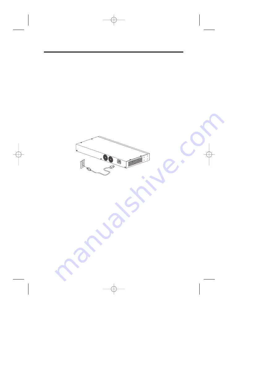
2. Please stretch and plug the cord into the power jack of the switch.
3. Check if the PWR LED lights up. If it lights up, then the switch is ready 

to be connected to the network. See Figure 2-2-1.

Figure 2-2-1 Connecting to the power

3

User's Manual

new ALW-3016-UM  10/13/99 11:27 AM  ›¶›– 3

Содержание ALW-3016

Страница 1: ...16 port 10 100Mbps Switch User s Guide Acer Switch ALW 3016 new ALW 3016 UM 10 13 99 11 27 AM 1 ...

Страница 2: ...ies merchantability or fitness for any particular purpose Any software described in this manual is sold or licensed as is Should the programs prove defective following their purchase the buyer and not this company its distributor or its dealer assumes the entire cost of all necessary servicing repair and any incidental or consequential damages resulting from any defect in the software Furthermore ...

Страница 3: ...Connecting to the power supply 3 2 3 Rack mounting 4 2 4 Connecting to computers 5 2 5 LEDs interface overview 5 Chapter 3 Apply a feasible networking 3 1 Connecting a hub switch to normal port 7 3 2 How to use uplink port 8 3 3 Application 8 Chapter4 Trouble shooting 9 Appendix Specification 10 II User s Manual new ALW 3016 UM 10 13 99 11 27 AM I I ...

Страница 4: ...o the ports check the LEDs and you can start networking And AcerSwitch also provides some advanced features only provided in some corporate products such as FAN error Advise you in advance to prevent the down of LAN or damage of the equipment 1 2 Product configuration The product configuration inside the package is shown in the figure 1 2 1 Please check the contents of the package if there is any ...

Страница 5: ...s of the front and rear panel of this switch as shown in Figure 2 1 and 2 2 Figure 2 1 Front panel Figure 2 2 Rear Panel 2 1 Installing the switch You have to find a solid working surface to place the switch and make sure the equipment is not close to any high voltage power source or over heated sources Also keep away from electronic equipment sensitive to electronic interface The brief procedures...

Страница 6: ...ge The procedure for connecting to the power will be 1 Place the switch on the desktop and remove the packing box of the power adapter 2 Please stretch and plug the cord into the power jack of the switch 3 Check if the PWR LED lights up If it lights up then the switch is ready to be connected to the network See Figure 2 2 1 Figure 2 2 1 Connecting to the power 3 User s Manual new ALW 3016 UM 10 13...

Страница 7: ...lied with the unit see Figure 2 3 4 Place the switch in the rack and align the holes in the mounting bracket with the holes in the rack chassis see Figure 2 4 5 Insert two mounting screws the rack mount equipment should provide these screws into each of the mounting brackets and tighten with a suitable screwdriver Figure 2 3 Attaching mounting brackets 8 screws M3x5 Figure 2 4 Attaching mounting b...

Страница 8: ...e switch 4 Turn on the PC and check if the Link LEDs on the adapter card and the switch Named as LNK ACT 100 LNK ACT 10 are lit up See Figure 2 4 1 If the LED is not lit up there must be something wrong and please reference to Chapter 4 for quick trouble shooting Figure 2 4 1 Connecting to computers 2 5 LEDs interface overview You can observe the LEDs status to see if the hub works fine The meanin...

Страница 9: ...uipment will work normally Note There are two Fan inside the ALW 3016 Fan Err1 Fan Err2 indicate the two Fans individually 2 5 2 Port indicators LNK ACT 100 LNK ACT 10 When the port is linked with 100Mbps device the LNK ACT 100 LNK ACT 10 will be lit on GREEN or it will be lit on orange with 10Mbps device And when there s any transmission activity in the port the LED will be blinking in GREEN with...

Страница 10: ...other hub switch with it s uplink port to the normal port of ALW 3016 See Figure 3 1 1 1 Place the hub switch on a stable surface 2 Use one end of the UTP STP cord to connect to the uplink port of the hub switch 3 Use the other end of the UTP STP cord to connect to the normal port of ALW 3016 4 Check the status of LNK ACT 100 LNK ACT 10 LED If the LNK ACT 100 LNK ACT 10 LED is lit on green then it...

Страница 11: ...itch 3 Make sure the LNK ACT 100 LNK ACT10 LED is lit then it will work normally See Figure 3 2 1 Figure 3 2 1 Up link port connection 3 3 Application With this application diagram you can clearly see the possibility what ALW 3016 can do for you in expand your network See Figure 3 3 1 Figure 3 3 1 Application diagram Notice Use UTP Cat 5 to connect to 100 Mbps equipment and UTP Cat 3 4 5 to connec...

Страница 12: ...ure ALW 3016 normal a hub or LAN switch port is connected to the other the connected ports signal hub s or switch s uplink port could be cross over and ALW 3016 uplink port is connected the other s normal port 5 The UTP cable is broken 5 Try another normal cable or it is cross overed cable 100 LED is not lit The auto negotiation 1 Check if you force the connection when connected function is failed...

Страница 13: ...T FDX for each port and Speed 10 100Mbps Switch Processing Scheme Store and forward Address Table supports up to 8K unicast addresses Cabling requirement UTP Cat 3 4 5 for 10Base T UTP Cat 5 for 100 Base TX Standards Conformance Standards IEEE 802 3 802 3u Environmental Operating temperature 0 50 C 32 122 F Operating humidity 20 80 non condensing EMI FCC Class A CE Class A VCCI Class 1 and C Tick ...

Страница 14: ...ays warranty or the remainder of the initial warranty period whichever is longer ANI shall not be responsible for any software firmware information or memory data of customer contained in stored on or integrated with any products returned to ANI pursuant to any warranty Before you obtain warranty service you must request an RMA Return Materials Authorization number by calling faxing or writing ANI...

Страница 15: ...Japan Corporation Tel 81 4 8290 1819 Fax 81 4 8290 1820 Acer Computer B V Tel 31 73 645 9645 Fax 31 73 645 9599 Acer UK Limited Tel 44 1628 533422 Fax 44 1628 524071 http www aceruk co uk Acer Computer France S A R L Tel 33 1 4817 4040 Fax 33 1 4817 4089 Acer Computer GmbH Tel 49 4102 488 0 Fax 49 4102 488 101 Dealers Information Hotline Germany 0180 3234781 End users Information Hotline Germany 0...

Страница 16: ...100 Recyclable Paper P N 49 23020 001 Acer Netxus Inc A Communications Company of Acer new ALW 3016 UM 10 13 99 11 27 AM 13 ...

Отзывы: