2-24
Service Guide
2.4
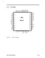
ALI M7101 (Power Management Unit)
2.4.1
Features
•
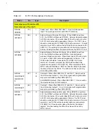
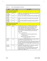
Four operating states - ON, DOZE, SLEEP, APM
•
Programmable DOZE and SLEEP timer
•
Programmable EL timer for backlight control
•
Two Programmable APM timers
•
Two output pins depending on operating state, each pin is programmable and power
configurable
•
Provides system activity and EL activity monitorings, includes
•
Video
•
Harddisk
•
Floppy
•
Serial port
•
Parallel port
•
Keyboard
•
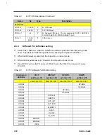
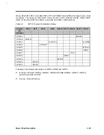
Six programmable I/O address groups activity monitor
•
Two programmable memory address groups activity monitor
•
Multiple external wake-up events from DOZE or SLEEP to ON states
•
External Push button
•
Cover open
•
Modem Ring
•
RTC alarm
•
DRQ
•
Two level battery warning monitors
•
24 General Purpose I/O pins. Each pin can be programmed to become input or output
•
32 External expandable general purpose output signals
•
32 External expandable general purpose input signals
•
LCD control
•
Rundown monitor detect
•
Suspend wake-up detect
•
100-pin PQFP package
Содержание AcerNote Light 370P
Страница 1: ...TI Extensa 61X Series AcerNote 370P Notebook Service Guide PART NO 2238309 0809 DOC NO PRINTED IN USA ...
Страница 6: ...vi ...
Страница 26: ...1 8 Service Guide Figure 1 5 Main Board Layout Bottom Side ...
Страница 49: ...System Introduction 1 31 1 5 1 3 Power Management Figure 1 14 Power Management Block Diagram ...
Страница 55: ...System Introduction 1 37 1 6 System Block Diagram Figure 1 15 System Block Diagram ...
Страница 64: ...Major Chips Description 2 7 2 2 5 Pin Diagram Figure 2 4 M1521 Pin Diagram ...
Страница 99: ...2 42 Service Guide 2 5 3 Pin Diagram Figure 2 10 C T 65550 Pin Diagram ...
Страница 116: ...Major Chips Description 2 59 2 6 4 Block Diagram Figure 2 11 Functional Block Diagram 16 bit PC Card Interface ...
Страница 117: ...2 60 Service Guide Figure 2 12 Functional block diagram CardBus Card Interface ...
Страница 118: ...Major Chips Description 2 61 2 6 5 Pin Diagram Figure 2 13 PCI to PC Card 16 bit terminal assignments ...
Страница 119: ...2 62 Service Guide Figure 2 14 PCI to CardBus terminal assignments ...
Страница 135: ...2 78 Service Guide 2 7 3 Pin Diagram Figure 2 16 NS87336VJG Pin Diagram ...
Страница 145: ...2 88 Service Guide 2 8 2 Pin Diagram Figure 2 17 YMF715 Block Diagram ...
Страница 185: ...Disassembly and Unit Replacement 4 5 Figure 4 3 Disassembly Sequence Flowchart ...
Страница 209: ...B 2 Service Guide ...
Страница 210: ...Exploded View Diagram B 3 ...
Страница 217: ...A p p e n d i x D A p p e n d i x D Schematics This appendix shows the schematic diagrams of the notebook ...


