BIOS Setup Information
3-11
3.5
Power Management Settings
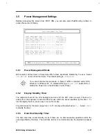
Besides accessing this screen from POST (F2), you can also press Fn-F6 during runtime to
access this section of Setup.
Power Management Settings
Power Management Mode ------------- [Enabled]
Display Standby Timer ------------- [ 1] Minute(s)
Hard Disk Standby Timer ----------- [ 1] Minute(s)
System Sleep Timer ---------------- [ 3] Minute(s)
System Sleep Mode ----------------- [Hibernation]
System Resume Timer Mode ---------- [Disabled]
System Resume Date ---------------- [--/--/----]
System Resume Time ---------------- [--:--:--]
Modem Ring Resume On Indicator ---- [Enabled]
Battery-low Warning Beep ---------- [Enabled]
Sleep Upon Battery-low ------------ [Enabled]
↑↓
=Move Highlight Bar,
→←
=Change Setting, F1=Help, Esc=Exit
3.5.1
Power Management Mode
With enabled, all the timers in Setup take effect unless specifically disabled by the user. Select
[Disabled]
to turn off all the timers. The default setting is
[Enabled]
.
You cannot disable this parameter in Setup if APM is installed under DOS,
Windows or Windows 95. To disable APM, type
Power Off
under DOS, or
disable the Power icon in the Windows Control Panel.
3.5.2
Display Standby Timer
The notebook shuts off the LCD backlight and turns off the CRT video as well, if there is no
activity from the keyboard or external PS/2 mouse within the period specified by this timer. To
turn the display back on, press a key or move the mouse.
The valid values for this timer range from 1 to 15 minutes with default set at
[1]
. Select
[Off]
to disable the timer.
3.5.3
Hard Disk Standby Timer
The hard disk drive enters standby mode if there are no disk read/write operations within the
period specified by this timer. The hard disk returns to normal mode once the notebook accesses
it.
Содержание AcerNote Light 370P
Страница 1: ...TI Extensa 61X Series AcerNote 370P Notebook Service Guide PART NO 2238309 0809 DOC NO PRINTED IN USA ...
Страница 6: ...vi ...
Страница 26: ...1 8 Service Guide Figure 1 5 Main Board Layout Bottom Side ...
Страница 49: ...System Introduction 1 31 1 5 1 3 Power Management Figure 1 14 Power Management Block Diagram ...
Страница 55: ...System Introduction 1 37 1 6 System Block Diagram Figure 1 15 System Block Diagram ...
Страница 64: ...Major Chips Description 2 7 2 2 5 Pin Diagram Figure 2 4 M1521 Pin Diagram ...
Страница 99: ...2 42 Service Guide 2 5 3 Pin Diagram Figure 2 10 C T 65550 Pin Diagram ...
Страница 116: ...Major Chips Description 2 59 2 6 4 Block Diagram Figure 2 11 Functional Block Diagram 16 bit PC Card Interface ...
Страница 117: ...2 60 Service Guide Figure 2 12 Functional block diagram CardBus Card Interface ...
Страница 118: ...Major Chips Description 2 61 2 6 5 Pin Diagram Figure 2 13 PCI to PC Card 16 bit terminal assignments ...
Страница 119: ...2 62 Service Guide Figure 2 14 PCI to CardBus terminal assignments ...
Страница 135: ...2 78 Service Guide 2 7 3 Pin Diagram Figure 2 16 NS87336VJG Pin Diagram ...
Страница 145: ...2 88 Service Guide 2 8 2 Pin Diagram Figure 2 17 YMF715 Block Diagram ...
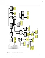
Страница 185: ...Disassembly and Unit Replacement 4 5 Figure 4 3 Disassembly Sequence Flowchart ...
Страница 209: ...B 2 Service Guide ...
Страница 210: ...Exploded View Diagram B 3 ...
Страница 217: ...A p p e n d i x D A p p e n d i x D Schematics This appendix shows the schematic diagrams of the notebook ...

