


2-92
Service Guide
•
Max. T
•
Safety charging timer
•
Battery temperature constantly monitoring
•
Over voltage protect 13V
•
Providing low battery warning signals when the system using battery as the main power
source
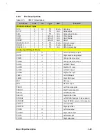
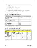
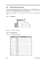
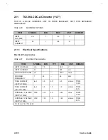
2.9.3
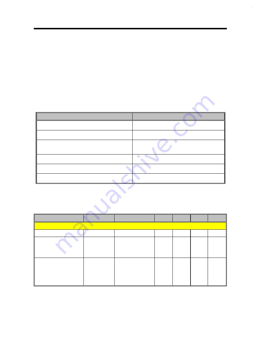
Absolute Maximum Ratings
Table 2-16
T62.062.C Absolute Maximum Ratings Table
Parameter
Maximum Ratings
Supply voltage ( Adapter)
0V to +24V
Output current
3A
Total sink current of all O/P pin
(output pin to DC/DC not included)
15mA
Charge current
1.9A
Operating temperature
0 to 60
Storage temperature
-10 to 85
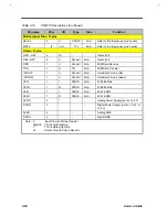
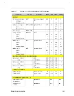
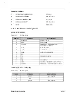
2.9.4
Electrical Characteristics
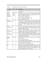
Table 2-17
T62.062.C Electrical Characteristics Table
Parameter
Symbol
Condition
MIN
TYP
MAX
UNITS
INPUT
External Adapter
AC power
*Note 1
19
20
21
V
Disable (High)
(Low)
(Supply current)
Disable
Delay about 10 ms
3.5
-
300
5
-
-
5.25
0.7
-
V
V
uA
System in use power
(High)
(Low)
(Supply current)
S.I.U.
4.0
-
1
5
-
-
5.25
2.0
-
V
V
mA
Содержание AcerNote Light 370P
Страница 1: ...TI Extensa 61X Series AcerNote 370P Notebook Service Guide PART NO 2238309 0809 DOC NO PRINTED IN USA ...
Страница 6: ...vi ...
Страница 26: ...1 8 Service Guide Figure 1 5 Main Board Layout Bottom Side ...
Страница 49: ...System Introduction 1 31 1 5 1 3 Power Management Figure 1 14 Power Management Block Diagram ...
Страница 55: ...System Introduction 1 37 1 6 System Block Diagram Figure 1 15 System Block Diagram ...
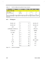
Страница 64: ...Major Chips Description 2 7 2 2 5 Pin Diagram Figure 2 4 M1521 Pin Diagram ...
Страница 99: ...2 42 Service Guide 2 5 3 Pin Diagram Figure 2 10 C T 65550 Pin Diagram ...
Страница 116: ...Major Chips Description 2 59 2 6 4 Block Diagram Figure 2 11 Functional Block Diagram 16 bit PC Card Interface ...
Страница 117: ...2 60 Service Guide Figure 2 12 Functional block diagram CardBus Card Interface ...
Страница 118: ...Major Chips Description 2 61 2 6 5 Pin Diagram Figure 2 13 PCI to PC Card 16 bit terminal assignments ...
Страница 119: ...2 62 Service Guide Figure 2 14 PCI to CardBus terminal assignments ...
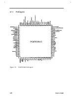
Страница 135: ...2 78 Service Guide 2 7 3 Pin Diagram Figure 2 16 NS87336VJG Pin Diagram ...
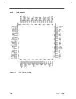
Страница 145: ...2 88 Service Guide 2 8 2 Pin Diagram Figure 2 17 YMF715 Block Diagram ...
Страница 185: ...Disassembly and Unit Replacement 4 5 Figure 4 3 Disassembly Sequence Flowchart ...
Страница 209: ...B 2 Service Guide ...
Страница 210: ...Exploded View Diagram B 3 ...
Страница 217: ...A p p e n d i x D A p p e n d i x D Schematics This appendix shows the schematic diagrams of the notebook ...


