


System Introduction
1-25
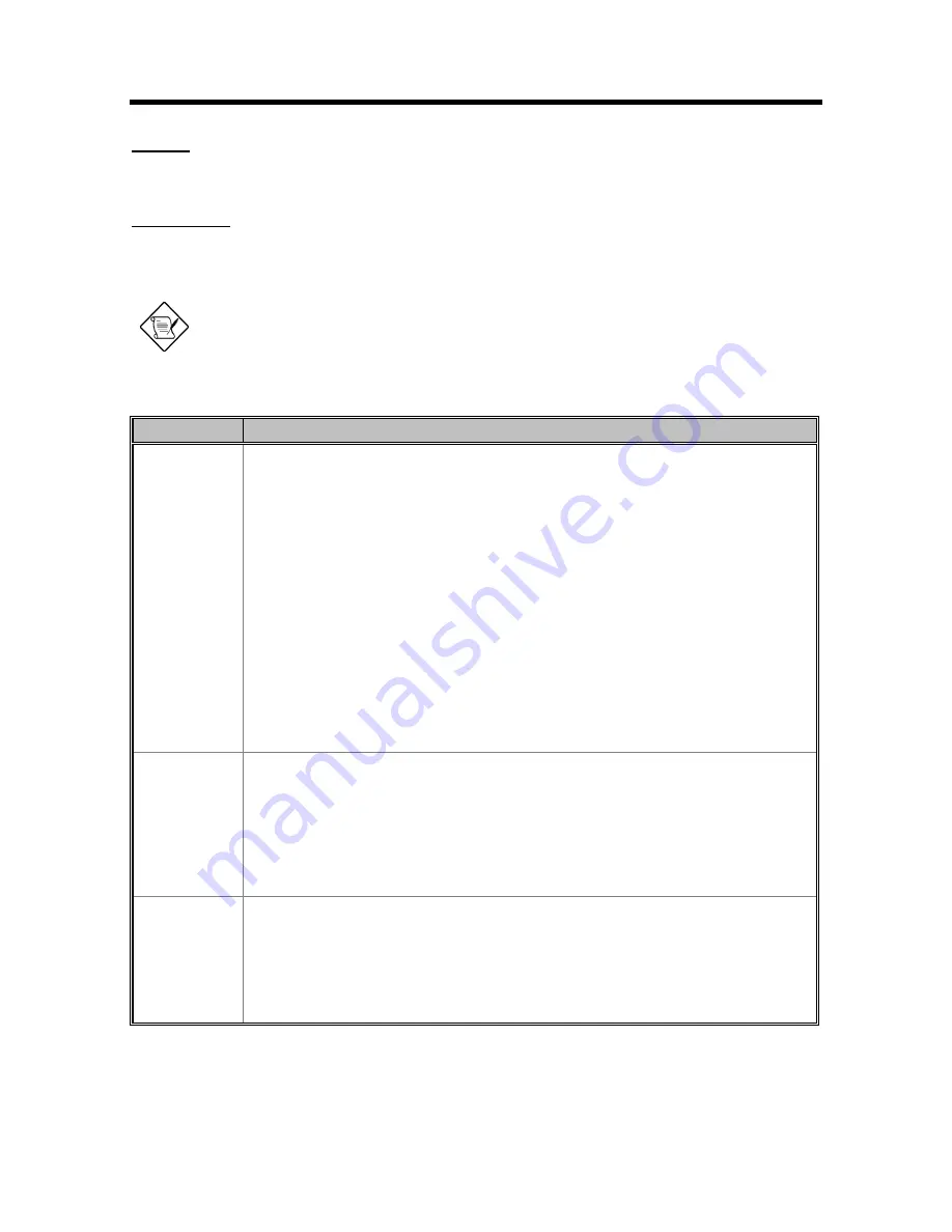
ON MODE
Normal full-on operation
STANDBY MODE
The computer consumes very low power in standby mode. Data remain intact in the system
memory until battery is drained.
Warning: Unstored data is lost when you turn off the computer power in standby
mode or when the battery is drained.
Table 1-31
Standby Mode Conditions and Descriptions
Condition
Description
The condition
to enter
Standby Mode
There are two necessary conditions for the computer to enter standby mode:
•
Heuristic Power Management Mode must be set to [ENABLED].
•
System Sleep State must be set to [STANDBY].
In this situation, the following are ways to enter standby mode:
•
Pressing the sleep hot key Fn-F7
•
If the waiting time determined by the computer’s HPM unit elapses without any
system activity.
•
Closing the display cover.
•
With the System Sleep State is set to [HIBERNATION], the computer also enters
standby mode if the hibernation file (Sleep Manager) is invalid or not present.
•
“Hard Disk Drive” is [Disabled] in System Security of BIOS SETUP.
•
“Hard Disk 0” is [None] in Basic System Configuration of BIOS SETUP.
Note: If the computer detects a PC I/O card installed in the PC card slots, the computer
"sleeps" (light green mode) to maintain your communications connection. It will not enter
standby mode.
The condition
of Standby
Mode
•
Issue a beep.
•
Light standby LED with 1 Hz frequency.
•
Disable the mouse, serial and the parallel port.
•
The keyboard controller, HDD and VGA enter the standby mode.
•
Stop the CPU internal clock.
•
All the functions are disabled except the keyboard, battery low warning and modem
ring wake up from standby (if enabled).
The condition
back to On
Mode
Any one of following activities will let system back to Normal Mode:
•
Any keystroke (Internal KB or External KB)
•
Any active pointing device (internal or external, PS/2 or serial or USB)
•
Resume Timer matched
•
Opening the display cover if you closed the display cover to enter Standby mode.
•
Modem ring
Содержание 390 Series
Страница 14: ...1 2 Service Guide 1 2 System Board Layout 1 2 1 Mainboard Figure 1 1 PCB No 96183 1A Mainboard Layout Top ...
Страница 15: ...System Introduction 1 3 Figure 1 2 PCB No 96183 1A Mainboard Layout Bottom ...
Страница 96: ...2 50 Service Guide 2 3 3 Pin Configuration Figure 2 4 FDC37C67 TQFP Pin Diagram ...
Страница 97: ...Major Chips Description 2 51 Figure 2 5 FDC37C67 QFP Pin Diagram ...
Страница 102: ...2 56 Service Guide 2 3 6 Block Diagram Figure 2 6 FDC37C67 Block Diagram ...
Страница 111: ...Major Chips Description 2 65 2 4 4 3 Bottom View BGA Ball Assignments Figure 2 8 65555 BGA Ball Assignments Bottom View ...
Страница 126: ...2 80 Service Guide 2 5 4 1 Functional Block Diagram Figure 2 10 M38813 Block Diagram ...
Страница 128: ...2 82 Service Guide 2 6 2 Pin Diagram Figure 2 11 YMF715 Block Diagram ...
Страница 168: ......
Страница 169: ......
Страница 170: ......
Страница 171: ......
Страница 172: ......
Страница 173: ......


