ACE COMPUTERS VS-M690I Скачать руководство пользователя страница 5

8/

2

6

/20

22


ACE144 
 

ENEGY STAR AND POWER MANAGEMENT 

What is Energy Star? 

Created  by  the  Environmental  Protection  Agency  (EPA)  and  the  United  States  Department  of 
Energy (DOE), the Energy Star program is a strict set of specifications that residential appliances 
and  construction  elements  (washers,  dryers,  refrigerators,  freezers,  dishwashers,  televisions, 
tablets,  computers,  monitors,  water  heaters,  HVAC  units,  dehumidifiers,  air  cleaners  and 
purifiers,  lighting,  insulation  and  more)  must  meet  through  evaluation  and  testing  to  achieve 
certification.  

The Energy Star rating assures consumers that the product has been EPA and DOE certified to 
function as well or better than its peers, while saving money, energy and the environment due 
to its greater energy efficiency. 

Benefits of Energy Star 


Increased Efficiency 


Reduced Energy Use 


Reduced Utility Bills 


Reduced Power Plant Emissions and Carbon Footprint 


Wide Selection, Rebates, and Convenience 

VS-M690I 

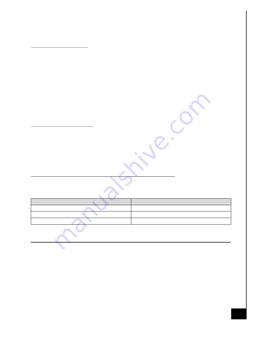
Power Management Settings “As Shipped” 


The default Power Management settings have been selected for compliance with Energy Star and 
are recommended by the Energy Star program for optimal energy savings.  

Power Management Option 

Setting 

System Sleep Mode 

After 30 min. of user inactivity 

Display Sleep Mode 

After 10 min. of user inactivity 

Primary Hard Drive 


“Hard Disk Turn Off”


20 min. 


How to wake your computers or monitor from Sleep or Hibernate Mode? 

To wake up your computer or monitor from sleep or hibernate, move the mouse or press any key 
on the keyboard. If this does not work, press the power button to wake up the computer. 


Содержание VS-M690I

Страница 1: ...8 26 2022 ACE144 1 TECHNICAL REFERENCE GUIDE ACE VISION SERIES MODEL VS M690I...

Страница 2: ...POWER MANAGEMENT 5 ILLUSTRATED SYSTEM DISASSEMBLY REASSEMBLY INSTRUCTIONS 7 TROUBLESHOOTING YOUR PC 33 MAINTENANCE 35 SOFTWARE UPDATES 36 REMOVAL OF PERSONAL DATA 37 UPGRADES SERVICE AND REPAIR 40 PRO...

Страница 3: ...ARDWARE SOFTWARE OR DATA Any disputes arising between manufacturer and customer shall be governed by the laws of Cook County in the State of Illinois USA The State of Illinois County of Cook shall be...

Страница 4: ...n to provide additional guidance on standard energy settings and configurable energy settings for the end user Resources If you have any questions regarding this manual or computer system please conta...

Страница 5: ...money energy and the environment due to its greater energy efficiency Benefits of Energy Star Increased Efficiency Reduced Energy Use Reduced Utility Bills Reduced Power Plant Emissions and Carbon Fo...

Страница 6: ...ttings if the manufacturer has control over such features WoL Wake on LAN WoL Capabilities Default Settings Yes No Has the ability to Enable and Disable WoL for Sleep Mode WoL Enables from Sleep by de...

Страница 7: ...ons are for demonstration only The system and components shown in this section are a representative sample Replacement Parts Refer to section UPGRADES SERVICE AND REPAIR for information on how to obta...

Страница 8: ...a representative sample of the VS M690I your PC may include additional components or variations of this family configuration Figure 1 Heat Sink Fan Processor Memory 2 4 DIMMs Power Supply Case Fans 8x...

Страница 9: ...ploded View of Representative Sample of VS M690I Model Exploded Diagram 1 Exploded Diagram 1 Legend No Component Description 1 Power Supply 2 Chassis 3 Optical Drive optional 4 Motherboard 5 Chassis F...

Страница 10: ...8 26 2022 ACE144 10 Exploded Diagram 2 Exploded Diagram 2 Legend No Component Description 4 Motherboard 7 Memory 8 Discrete Graphics Card 9 M 2 SSD 10 Heatsink 11 CPU 4 7 8 9 10 11...

Страница 11: ...the left side rear top and bottom at the rear of the chassis Step 3 Once removed slide the chassis side panel parallel to the chassis towards the rear this will disengage the various tabs that are hol...

Страница 12: ...bottom of the chassis Turn the chassis on the side the screws are located on the bottom of the chassis While you are unfastening the screws be sure to secure the HDD so it does not fall and damage an...

Страница 13: ...river then pull straight back in a parallel position to remove the M 2 SSD from the slot on the motherboard Reinstallation Step 4 Gently slide the M 2 SSD into the designated slot as noted in the phot...

Страница 14: ...ends of the memory module to unlock the carriage Use gentle even force on either side of the memory module to remove from the memory slot Step 4 Repeat Step 3 for each piece of memory in the system Re...

Страница 15: ...r section of this manual Step 3 Remove 4x Phillips screws from the base of the heatsink module Once all 4 Phillips screws are removed you will be able to remove the heatsink module off the processor s...

Страница 16: ...e them Step 5 Pull up the push pins Step 6 Remove the fan Reinstallation Step 7 Turn the push pins clockwise 90 degrees to reset them Step 8 Reinsert the fan and find the push pins Step 9 Press the pu...

Страница 17: ...al energy is dissipated Step 2 Remove the side panel from the chassis as indicated in the Chassis Cover section of this manual Step 3 To access the CPU the heatsink must first be removed refer to heat...

Страница 18: ...installation of a processor specifically ensure to utilize a thermal paste between the top of the process and the bottom of the heat sink this allows for the best thermal heat transfer and effective...

Страница 19: ...d and any potential energy is dissipated Step 2 Remove the side panel from the chassis as indicated in the Chassis Cover section of this manual Step 3 Remove the Phillips screws from the rear of the c...

Страница 20: ...Z690 P D4 Disposal Selective Treatment Special Handling Per Annex VII Directive 2012 19 EU Graphics and add on expansion cards contain a printed circuit board of greater than 10 sq cm and must be remo...

Страница 21: ...rom the various internal components as applicable Step 5 Gently slide the power supply out of the case When removing the connectors from the motherboard use caution some connectors have latching clips...

Страница 22: ...D SATA Power to Optical Drive Motherboard Diagram for PSU Connections Disposal Selective Treatment Special Handling Per Annex VII Directive 2012 19 EU The motherboard is a printed circuit board of gre...

Страница 23: ...nergy is dissipated Step 2 Remove the side panel from the chassis as indicated in the Chassis Cover section of this manual Step 3 Remove all peripheral components on the motherboard the details of the...

Страница 24: ...d in this Technical Reference Guide For additional details on reinstallation of the motherboard and any peripheral components of the motherboard refer to the motherboard user manual for ASUS Prime Z69...

Страница 25: ...energy is dissipated Step 2 Remove the side panel from the chassis as indicated in the Chassis Cover section of this manual Step 3 Gently push aside the small clamp that covers the edge of the battery...

Страница 26: ...rewdriver Procedure Step 1 Ensure the computer is off unplugged and any potential energy is dissipated Step 2 Remove the side panel from the chassis as indicated in the Chassis Cover section of this m...

Страница 27: ...screws in the location noted below to secure the fan to the chassis Step 8 Connect the fan header cable to the motherboard for power CHA_FAN1 see motherboard diagram for reference Disposal Selective...

Страница 28: ...nergy is dissipated Step 2 Remove the side panel from the chassis as indicated in the Chassis Cover section of this manual Step 3 Locate the speaker and gently but firmly pull away from motherboard co...

Страница 29: ...rated into the graphics card as applicable Procedure Note I O connections are integral parts of higher level assemblies and thus to replace them the entire assembly would need to be replaced To uninst...

Страница 30: ...ential energy is dissipated Step 2 Remove the side panel from the chassis as indicated in the Chassis Cover section of this manual For removal of the optical drive both chassis covers will need to be...

Страница 31: ...ng from the front and 1 screw on the right side of the chassis when looking from the front Step 11 Reconnect SATA power header to optical drive from PSU and SATA data cable from optical drive to mothe...

Страница 32: ...supply is in the off position Step 2 Disconnect the external power cable from the main desktop assembly Reinstallation Step 3 Connect the external power cable from the rear of the chassis into the pow...

Страница 33: ...oper rear port 1 Check all the connection s on the video card and your monitor make sure they are fully seated 2 Select the correct source on your monitor 3 If available use a different display cable...

Страница 34: ...try uninstalling any recently installed hardware drivers perform a system restore and scan for malware Newly installed drivers or malicious software may be causing this issue 3 If your computer is st...

Страница 35: ...to let the unit set for a few minutes pressing the on off button a few times to dissipate any energy the capacitors may be storing 2 Compressed air is a great tool to remove dust quickly and safely Re...

Страница 36: ...click on the Check for updates button to see if your system needs updates 3 We highly recommend checking Windows Updates often as security is extremely important Periodic Update of Device Drivers It i...

Страница 37: ...pdate Security Recovery Open Recovery Settings Step 2 Under Reset this PC select Get Started and then choose from the options and or setting in the table below Option What it Does Keep my files Change...

Страница 38: ...tection equipment eg Safety glasses gloves etc when working with tools power tools or using blunt force to destroy an HDD Use good judgment and caution HDD There are several ways to disable destroy a...

Страница 39: ...simpler it can simply be destroyed beyond use there is no protective outer cover Use of a hammer stomping on the component breaking in half etc are all simple examples of how to destroy the SSD beyon...

Страница 40: ...for several years beyond the initial 3 year mark ensuring the longest possible utilization of your PC Hardware Features Upgradeable Repairable Replaceable Chassis Motherboard including ethernet CPU CP...

Страница 41: ...onent Description Part Number Chassis JS513 NPS Motherboard ASUS Prime Z690 P D4 CPU XXXXXXYYY CPU Spare Part CPU Heatsink XXXXXXYYY CPU Heatsink Spare Part Power Supply XXXXXXYYY PSU Spare Part Case...

Страница 42: ...et the product back and will ensure it is proper disposed of with a certified R2 electronics recycling facility Ace Computers has partnered with a local R2 certified electronics waste recycling facili...

Страница 43: ...8 26 2022 ACE144 43 REVISION HISTORY Release Date Changes 8 26 2022 Initial Release...

Отзывы: