background image

1

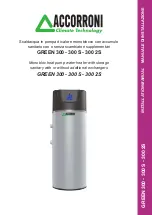
GREEN 300 - 300 S - 300 2S

Scaldacqua in pompa di calore monoblocco con accumulo

sanitario con o senza scambiatori supplementari

GREEN 300 - 300 S - 300 2S

Monobloc heat pump water heater with storage

sanitary with or without additional exchangers

GREEN 300 - 300 S - 300 2S

INST

ALLA

TION MANUAL


 MANUALE DI INST

ALLAZIONE

Содержание GREEN 300

Страница 1: ... monoblocco con accumulo sanitario con o senza scambiatori supplementari GREEN 300 300 S 300 2S Monobloc heat pump water heater with storage sanitary with or without additional exchangers GREEN 300 300 S 300 2S INSTALLATION MANUAL MANUALE DI INSTALLAZIONE ...

Страница 2: ...5 5 2 Table user parameters 5 5 3 Table manufacturer parameters 5 6 Alarm description 6 CONTROLS BEFORE STARTUP 7 ROUTINE MAINTENANCE 7 1 Warning 7 2 Monthly checks 7 3 Quarterly checks 7 4 Yearly checks 8 TROUBLESHOTING 9 DISPOSAL pag 2 Manuale di installazione Uso e Manutenzione Installation Use and Maintenance Manual INDICE SIMBOLOGIA UTILIZZATA 3 AVVERTENZE E REGOLE GENERALI 3 NOTE IMPORTANTI ...

Страница 3: ...tto utilizzodella macchina sono accompagnate da alcuni simboli per renderle più evidenti The machine has been designed and constructed according to the current norms and consequently with mechanical and electrical safety devices designed to protect the operator or user from possible physical damage Residual risks during use or in some intervention procedures on the device are however present such ...

Страница 4: ...patible with toxic explosive inflammable and corrosive chlorinated and saline included gases Therefore it cannot be used in those environments where the air is mixed and or altered by other gaseous composites and or solid particles The use of the same for different purposes from those envisioned not conform to that described in this manual will make any direct and or indirect liability of the manu...

Страница 5: ...IONE IDENTIFICATION PLATE A A IDENTIFICAZIONE UNITÀ IDENTIFICATION UNIT PER EVENTUALI RICHIESTE DI INFORMAZIONI È NECESSARIO RIVOLGERSI ALLA SEDE COMUNICANDO IL NUMERO DI SERIE DELL UNITÀ WHEN CONTACTING THE OFFICE FOR ANY INFORMATION ENQUIRIES PLEASE PROVIDETHE UNIT SERIAL NUMBER ...

Страница 6: ...6 1 CARATTERISTICHE TECNICHE 1 TECHNICAL SPECIFICATIONS 1 1 DESCRIZIONE GENERALE 1 1 GENERAL DESCRIPTION 0 1 09 GREEN GREEN GREEN GREEN GREEN GREEN ...

Страница 7: ...rated sonde for the control of water temperature Outdoor temperature sensor for automatic insertion of the resistance with temperature not favourable to the heat pump NTC sonde imput output evaporator battery Eletronic expansione valve Solenoid valve for injection of gas hot Magnesium anode anti corrosion Electronic anode available as accessory Hydraulic connections on the back side Thermal insula...

Страница 8: ...ica refrigerante R134a Refrigerant charge R134a Kg 1 5 Max pressione circuito frigo lato alta pressione Maximum pressure cooling circuit side hight pressure bar 25 Potenza resistenza elettrica Electric power resistance W 1500 Corrente assorbita resistenza elettrica Absorbed current eletric resistence A 6 3 Portata d aria Air flow mc h 450 Pressione statica utile Static pressure pa 80 Temperatura a...

Страница 9: ...vo acqua calda Outlet Hot water Rp 1 2 Mandata riscaldamento Outlet heating Rp 1 3 Ricircolo Recirculation Rp 1 2 4 Ritorno riscaldamento Inlet heating Rp 1 5 Mandata solare Outlet solar Rp 1 6 Ritorno solare Inlet solar Rp 1 7 Scarico condensa Condensate drain Rp 1 2 8 Ingresso acqua fredda Inlet cold water Rp 1 9 Resistenza elettrica Electric heater Rp 1 1 4 10 Anodo Anode Rp 1 1 4 11 Pozzetto s...

Страница 10: ...h single machine is reported on this manual Avoid rotations out of control Accurate care should be taken when loading operations all machines must be loaded and stowed in the truck by inserting suitable spacers safeguarded for all protruding parts such as water connections or heater For manual transport you can use the wooden pallet The COMPACT unit is equipped with a handle to facilitate transpor...

Страница 11: ...he indicator of TILT WATCH red marks WARNING Packaging elements must be left out of children as sources of danger of suffocation 2 4 STOCCAGGIO 2 4 STORAGE In caso di stoccaggio prolungato mantenere le macchine protette dalla polvere e lontano da fonti di vibrazioni e di calore La Ditta Costruttrice declina ogni responsabilità per danneggiamenti dovuti a cattivo scarico o per mancata protezione da...

Страница 12: ...ed in the standards During installation operate in complete safety clean environment and free from obstructions Respect the laws in force in the country in which the machine is installed relative to use and disposal of packaging and the products used For cleaning and maintenance of the machine as well as complying with that recommended by the producer of these products Before starting the unit che...

Страница 13: ...rezza del prodotto Verificare che l ambiente di installazione e gli impianti elettrico ed idrico a cui deve connettersi l apparecchio siano conformi alle normative vigenti Place the unit on a flat surface capable of supporting the weight of the product and its contents Do not place the unit in an area where there are flammable acidic aggressive substances and which can damage the various component...

Страница 14: ...ilizzo di un addolcitore in modo che la durezza residua non sia superiore a 30 F prevedere l eventuale l installazione di una valvola miscelatrice termostatica sull uscita acqua calda per prevenire il rischio di ustioni Disconnect the boiler from the system before carrying out electric welding Flush the system before connecting boiler Install a safety valve and an expansion tank of adequate capaci...

Страница 15: ...i evitino il ricircolo di aria tra aspirazione e mandata della macchina siano collegate e fissate saldamente al prodotto per evitare accidentali scollegamenti siano adeguatamente protetti per evitare intrusioni accidentali di materiali all interno della macchina They do not rest on the unit Maintenance operations of the unit are enabled They avoid recirculation of air between inlet and outlet of t...

Страница 16: ...tandards Their size must be such as to achieve a voltage drop less than 3 of the nominal one Per l alimentazione generale della pompa di calore non è consentito l uso di adattatori prese multiple e o prolunghe E dovere dell installatore prevedere il montaggio il più vicino possibile all unità del sezionatore dell alimentazione e quanto necessario per la protezione delle parti elettriche Collegare ...

Страница 17: ...to Impostare il modo di funzionamento Impostare i parametri modificabili dall utente Gestire le situazioni di allarme Verificare lo stato delle risorse Set the operative mode Set the user parameters Alarms management Check the status of outputs 5 2 INTERFACCIA UTENTE FIG 9 5 2 USER INTERFACE FIG 9 Fig 9 1 Display 2 Tasto UP 3 Tasto DOWN 4 Tasto SET 5 Tasto ON OFF 6 Tasto FUNZIONE 1 Display 2 Key U...

Страница 18: ...legionella L17 Led attivazione funzione BOOST L18 Led attivazione funzione Manuale L19 Led attivazione funzione Auto L1 Led key ON OFF L2 Led activation compressor L3 Led activation resistance L4 Led key boiler L5 Led activation defrosting L6 Led atctivation circulator not active L7 Led activation resistance of contactON OFF L8 Led activation function HIGH L9 Led activation function clock L10 Led ...

Страница 19: ...uovamente il tasto ON OFF si riporta l unità in Off KEY ON OFF When the device is switched on the display will shows time Pressing the key ON OFF it has the units on and the display shows the water temperature inside the boiler sonde S01 Pressing again the key ON OFF it turns the unit on Off TASTO FUNZIONE Permette la selezione ciclica dei vari modi di funzionamento A ciascuna pressione del tasto ...

Страница 20: ...Change the parameters increase UP decrease DOWN The key DOWN pushing it for three seconds resets counter PdC resistance and the operation of total hours UP key silent the buzzer of antibacterial treatment and reset it TASTO SET Consente di confermare la selezione del modo di funzionamento prescelto accedere alla lista dei parametri visualizzare il parametro prescelto confermare la variazione del p...

Страница 21: ...ROLLER OPERATION 5 3 DESCRIZIONE INGRESSI USCITE SCHEDA ELETTRONICA SCHEDA ELETTRONICA FIG 10 5 3 IN OUT ELECTRONIC BOARD ELECTRONIC BOARD FIG 10 Fig 10 pag 22 Manuale di installazione Uso e Manutenzione Installation Use and Maintenance Manual ...

Страница 22: ... FVD consenso valvola sbrinamento USCITE DIGITALI INT GND contatto pulito per consenso caldaia EXPANSION controllo valvola espansione elettronica ID1 ID2 ID3 ID4 S01 S02 S03 S04 r2 r3 r1 r4 r7 r8 DIGITAL INPUTS HP GND high pressure BP GND Low pressure only predisposition RES GND Electrical heater remote ON OFF TIMER GND Unit remote ON OFF ANALOG INPUTS S1 GND Water Temperature S2 GND Outdoor air t...

Страница 23: ...ZIONE è possibile accedere alle varie modalità di funzionamento A ciascuna pressione del tasto corrisponde la selezione di un diverso modo di funzionamento segnalato dall accensione in modalità lampeggiante del led corrispondente Premendo il tasto SET si conferma l attivazione della modalità di funzionamento scelta Il led corrispondente si accende in modalità fissa E possibile disattivare le modal...

Страница 24: ...1 è inferiore al set point Ut1 ma sono attivi i ritardi impostati tramite i parametri h20 e h21 il led L2 sarà acceso in modalità lampeggiante se la pdc è attiva e la temperatura letta dalla sonda S01 è inferiore al set point Ut1 il led L2 sarà acceso in modalità fissa se il set point Ut1 è raggiunto o superato il led L2 sarà spento if the temperature read the S01 sonde is below the set point Ut1 ...

Страница 25: ...heat exchanger Using the digital output between the INT GND terminals clean contact according to the diagram below the status is displayed in the synoptic branch to r7 parameter 1 enabled 0 Off MANUALE Il controllo attiva la resistenza elettrica o la caldaia in funzione del valore del parametro H50 visto precedentemenmte L attivazione della caldaia o altra fonte integrativa vale solo per i modelli...

Страница 26: ... il controllo segnala tramite il lampeggio del led L16 e l attivazione del cicalino che è necessario eseguire un trattamento antibatterico A display si alternano la temperatura corrente e la scritta SERV premendo il tasto SET ha inizio l innalzamento della temperatura ad opera della resistenza o caldaia ih funzione del valore associato al parametro H50 Durante il trattamento sono accesi in modalit...

Страница 27: ... attivare la modalità 5D TIME SLOT 5 DAYS 5D You can set one daily time program effective from Monday to Friday To activate the mode 5D premere il tasto FUNZIONE fino a far lampeggiare il led 10 5D premere il tasto SET per confermare quindi il led L10 risulta acceso fisso ed il led L13 ON lampeggiante premere i tasti DOWN per modificare l orario di accensione premere in tasto SET per confermare l ...

Страница 28: ...UTOSTART La funzione Autostart consente la ripartenza automatica dell unità a seguito di uno spegnimento causato da una mancanza di tensione Attenzione è possibile abilitare disabilitare la funzione agendo sul parametro H23 PROGRAMMING It provides access to branches CFn PUP dFr Fan ALL EXV as described in the navigation diagram on Fig 19 20 Access to programming is reported the led L12 The path of...

Страница 29: ...one valore compreso tra 15 e 25 H36 escursione dell aria esterna su cui lavora il Set point valore compreso tra 5 e 10 H34 Slope of the compensation value between 0 5 and 2 H35 Outdoor air temperature above which the compensation starts value between 15 and 25 H36 Excursion of outdoor air temperature on which the setpoint works value between 5 and 10 Attenzione è possibile abilitare disabilitare l...

Страница 30: ...ntribution of this becomes ineffective to activate the HP To do this the unit can be switched ON OFF by digital input N O volt free terminals GND TIMER WARNING It is possible to enable disable the Remote ON OFF setting the parameter H70 H70 0 funzione disabilitata H70 1 funzione abilitata H70 0 Function Disabled H70 1 Function Enabled Con la funzione abilitata H70 1 alla pressione del tasto FUNZIO...

Страница 31: ...la resistenza in funzione del suo algoritmo di calcolo Il led L7 è spento Se il contatto RES GND è CHIUSO equivalente alla condizione Tariffa bioraria non conveniente l unità funziona normalmente solo che viene inibito l intervento della resistenza In tale modalità qualunque richiesta di intervento della resistenza viene segnalato dal led L7 acceso in modalità lampeggiante ad indicare che è in att...

Страница 32: ...eratura di massima velocità del ventilatore Rappresenta il differenziale rispetto ad f5 per la temperatura aria sotto la quale il ventilatore viene attivato alla massima velocità più l aria è fredda maggiore sarà la velocità del ventilatore F03 Minimum fan speed of maximum voltage F04 Maximum fan speed of maximum voltage F05 Temperature for minimum fan speed It represents the air temperature above...

Страница 33: ...r than F07 parameter 15 C the fan runs at max velocity F04 If the water temperature is higher or same as F07parameter 15 C it is possible to have 3 cases 1 CaseTair F05 F06 Fan at max velocity or F04 2 Case F05 F06 Tair F05 Fan at proportional velocity V 3 Case Tair F05 Fan at minimal velocity F03 DEFROST MANAGEMENT Menu dFr Allows to push the unit to be air temperatures next to 0 C preventing the...

Страница 34: ...onamento non appena il guasto viene riparato e la condizione di corretto funzionamento ripristinata Note that the occurrence of these failures does not cause any kind of damage to the device which resumes normal operation as soon as the fault is repaired and the condition of correct operation restored pag 35 Manuale di installazione Uso e Manutenzione Installation Use and Maintenance Manual ...

Страница 35: ...CONTROLLER OPERATION 5 5 DIAGRAMMA DEI MESSAGGI 5 5 1 DIAGRAMMA COMPLESSIVO fig 19 20 5 5 CHART OF THE MESSAGES 5 5 1 OVERALL CHART fig 19 20 Fig 19 pag 36 Manuale di installazione Uso e Manutenzione Installation Use and Maintenance Manual ...

Страница 36: ...36 5 FUNZIONAMENTO DEL CONTROLLORE 5 CONTROLLER OPERATION Fig 19A pag 37 Manuale di installazione Uso e Manutenzione Installation Use and Maintenance Manual ...

Страница 37: ...37 5 FUNZIONAMENTO DEL CONTROLLORE 5 CONTROLLER OPERATION Fig 20 pag 38 Manuale di installazione Uso e Manutenzione Installation Use and Maintenance Manual ...

Страница 38: ...38 5 FUNZIONAMENTO DEL CONTROLLORE 5 CONTROLLER OPERATION Fig 20A pag 39 Manuale di installazione Uso e Manutenzione Installation Use and Maintenance Manual ...

Страница 39: ...rametro Interno Internal parameter 2 H20 18 0 255 sec 10 Tempo minimo tra lo spegnimento e l accensione Tempo OFF ON espresso in decine di sec Minimum time between switching off and switching on Time OFF ON 2 H21 20 0 255 sec 10 Tempo minimo tra due accensioni successive Tempo ON ON espresso in decine di sec Minimum time between two successive starts Time ON ON 2 H22 30 0 255 sec Tempo di permanen...

Страница 40: ...From 40 to100 2 F04 100 F03 100 Num 1 Massima velocità espressa come percentuale da f03 a 100 Maximum fan speed of maximum voltage From F03to100 2 F05 30 0 50 C Temperatura aria sopra la quale il ventilatore deve essere attivato alla minima velocità Temp for minimum fan speed It represents the air temperature above which the fan runs at minimum speed 2 F06 6 0 10 C Differenziale di temperatura di ...

Страница 41: ...ne sul display della label E07 ALLARME ALTA TEMPERATURA Il riarmo è automatico Viene attivato se la Sonda S1 assume valori superiori al parametro AL5 per un tempo superiore al parametro AL6 L intervento comporta lo spegnimento della macchina e la visualizzazione sul display della label E05 5 6 ALARMS DESCRIPTION HIGH PRESSURE ALARM Automatic reset up to a number of times hour equal to the value se...

Страница 42: ...n it OFF and contact an authorized service centre indicating the identification data listed on the nameplate 6 CONTROLLI PRIMA DELL AVVIO 6 CONTROLS BEFORE STARTUP Prima di avviare l unità verificare Before start up check La corretta esecuzione dei collegamenti elettrici e la connessione del cavo di terra La corretta esecuzione dei collegamenti idraulici La connessione del raccordo scarico condens...

Страница 43: ...s easily solved ANOMALIE POSSIBILI CAUSE La pompa di calore non si accende non c è elettricità l interruttore principale del circuito è aperto Non partono il compressore e o il ventilatore non sono ancora trascorsi i tempi di sicurezza impostati il sistema è soddisfatto nessuna richiesta di carico il collegamento elettrico è allentato Partenze ed arresti ripetuti della pompa di calore sono errati ...

Страница 44: ...materiali che compongono le pompe di calore COMPACT sono The symbo l fig 21 indicates that this product must not be disposed of as mixed urban waste and that it must be collected separately according to local laws and regulations Contact local authorities for information on disposal options When purchasing a new equipment equivalent to the one to be disposed of the latter can be delivered to the d...

Страница 45: ...45 ...

Страница 46: ...46 ...

Страница 47: ...47 ...

Страница 48: ...titolo puramente indicativo la A2B Accorroni E G S r l si riserva di apportare eventuali modifiche senza alcun preavviso web site www accorroni it e mail a2b accorroni it A2B Accorroni E G s r l Via d Ancona 37 60027 Osimo An Tel 071 723991 ...

Отзывы: