


A111 Pulsed Coherent Radar (PCR)
Datasheet, v1.8
© 2019 Copyright by Acconeer
2019-06-12
Page 12 of 34
5
Timing Requirements
5.1 Serial Peripheral Interface
The Serial Peripheral Interface (SPI) is a 4-wire serial bus, used for configuration and reading output
from the A111 radar sensor. The A111 radar sensor is an SPI slave device connected to the SPI
master, as described in figure 5.1. The A111 allows several devices to be connected on the same SPI
bus, with a dedicated slave-select signal. Daisy-chain is not supported.
Host
(SPI Master)
A111
(SPI Slave)
A111
(SPI Slave)
SPI_CLK
SPI_MOSI
SPI_SS1
SPI_SS2
SPI_MISO
Figure 5.1. SPI master-slave connection
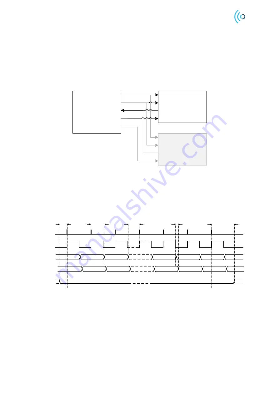
The serial data transfer input (MOSI) and output (MISO) to the A111 are synchronized by the
SPI_CLK. The Slave Select signal (SS) must be low before and during transactions. The MOSI is
always read on the rising edge of SCLK and the MISO changes value on the falling edge of SPI_CLK
(SPI mode 0, CPOL/CPHA = 0). SS requires release in between transactions. See figure 5.2 and table
5.1 for timing characteristics.
SPI_ClK
MOSI
MISO
SS
SS setup time
MSB
MOSI hold time
MOSI setup time
MISO propagation delay
SS hold time
LSB
15
15
14
14
13
13
0
0
1
1
2
2
Figure 5.2: Timing diagram of SPI, CPOL=0 and CPHA=0.