


10. Timer0/1/2/3
MC97F6108A User’s manual
84
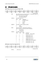
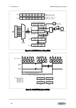
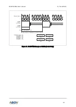
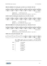
10.3
16-bit capture mode
The 16-bit capture mode of timer0/1/2/3
is set by CAPx as ‘1’ in TxCR register. The clock is
the same
source as 16-bit timer/counter mode. Interrupt occurs at TxH/TxL and TxDRH/TxDRL matching time.
The capture result is loaded into CDRxH/CDRxL. TxH/TxL values are automatically cleared (0000
H
) by
hardware and restarts counter.
This timer interrupt in the capture mode is very useful when the pulse width of captured signal is wider
than the maximum period of timer. And, external interrupt function (EINT0/1/2) is chosen by the EIEDGE
and EIPOLA and EIBOTH register setting.
CDRxH, PWMxDRH and TxH are in same address. In the capture mode, reading operation is to read
CDRxH, not TxH because path is opened to CDRxH. PWMxDRH will be changed in writing operation.
PWMxDRL, TxL and CDRxL has the same function.
P
R
E
S
C
A
L
E
R
÷ 1
÷ 4
÷ 8
÷ 16
÷ 64
÷ 256
÷ 1024
÷ 2048
TxH(8-bit)
TxL(8-bit)
16-bit Counter
TxST
TxEN
4
ECEN,TxCK[2:0]
f
X
TxIF
Timerx
Interrupt
-
-
TxIN[2] TxIN[1] TxIN[0]
ECEN
TxPE
POL
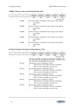
TxCR
TxCR1
ADDRESS : B2
H
, BA
H
, C2
H
, CA
H
INITIAL VALUE : 0000_0000
b
ADDRESS : B3
H
, BB
H
, C3
H
, CB
H
INITIAL VALUE : --00_0000
b
comparator
TxDRH(8-bit)
TxEN
PWMxE
CAPx
TxCK2
TxCK1
TxCK0
TxCN
TxST
3
TxDRL(8-bit)
CDRxH(8-bit)
CDRxL(8-bit)
clear
EIEDGE[A5
H
]
EIPOLA[A6
H
]
EIBOTH[A7
H
]
16-bit Capture Register
16-bit Timer Data Register
TxIN[2:0]
010
011
100
CAPx
TxEC0
TxEC1
3
TxIN[2:0]
000
001
0000
0001
0010
0011
0100
0101
0110
0111
1xxx
CIEDGE[AD
H
]
CIPOLA[AE
H
]
CIBOTH[AF
H
]
TxCAP0
TxCAP1
TxCAP2
Figure 28. 16-bit Capture Mode of Timer0/1/2/3