


6. Interrupt controller
MC97F6108A User’s manual
52
6.5
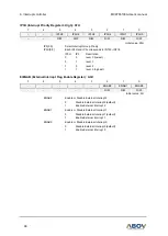
Interrupt sequence
An interrupt request is held until the interrupt is accepted or the interrupt latch is cleared t
o ‘0’ by a reset
or an instruction. Interrupt acceptance always generates at last cycle of the instruction. So instead of
fetching the current instruction, CPU executes internally LCALL instruction and saves the PC at stack.
For the interrupt service routine, the interrupt controller gives the address of LJMP instruction to CPU.
Since the end of the execution of current instruction, it needs 3 to 9 machine cycles to go to the interrupt
service routine. The interrupt service task is terminated by the interrupt return instruction [RETI]. Once
an interrupt request is generated, the following process is performed.
Figure 15. Interrupt Sequence Flow
Saves PC value in order to continue
process again after executing ISR
IE.EA Flag
0
1
Program Counter low Byte
SP
SP + 1
M (SP)
(PCL)
2
Program Counter high Byte
SP
SP + 1
M (SP)
(PCH)
3
Interrupt Vector Address occurrence
(Interrupt Vector Address)
4
ISR (Interrupt Service Routine) move,
execute
5
Return from ISR
RETI
6
Program Counter high Byte recovery
(PCH)
M (SP), SP
SP - 1
7
Main Program execution
10
Program Counter low Byte recovery
(PCL)
M (SP), SP
SP - 1
8
IE.EA Flag
1
9