


MC97F6108A User’s manual
20. Electrical characteristics
227
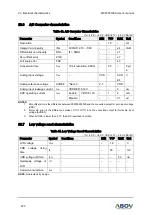
20.14
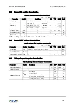
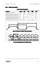
USART characteristics
Table 51. USART Characteristics
(T
A
= -40°C ~ +85°C, VDD=2.7V ~ 5.5V, f
IRC
=8MHz)
Parameter
Symbol
MIN
TYP
MAX
Unit
Serial port clock cycle time
t
SCK
1800
t
CPU
x 16 2200
ns
Output data setup to clock rising edge
t
S1
8100
t
CPU
x 13
–
ns
Clock rising edge to input data valid
t
S2
–
–
590
ns
Output data hold after clock rising edge t
H1
t
CPU
- 50
t
CPU
–
ns
Input data hold after clock rising edge
t
H2
0
–
–
ns
Serial port clock High, Low level width
t
HIGH
, t
LOW
720
t
CPU
x 8
1280
ns
t
HIGH
t
LOW
t
SCK
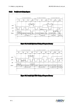
Figure 109. Waveform for USART Timing Characteristics
Shift Clock
Data Out
D1
D2
D3
D4
D5
D6
D7
D0
Valid
Data In
Valid
Valid
Valid
Valid
Valid
Valid
Valid
t
SCK
t
S1
t
H1
t
H2
t
S2
Figure 110. Timing Waveform for the USART Module