


MC97F6108A User’s manual
18. Reset
197
18.7
Register description for reset operation
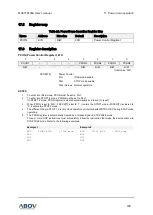
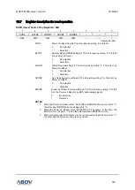
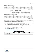
RSFR (Reset Source Flag Register): 86H
7
6
5
4
3
2
1
0
PORF
EXTRF
WDTRF
OCDRF
BODRF
–
–
–
R/W
R/W
R/W
R/W
R/W
–
–
–
Initial value: 88H
PORF
Power-On Reset flag bit. The bit is reset by writing
‘0’ to this bit.
0
No detection
1
Detection
EXTRF
External Reset (RESETB) flag bit. The bit is reset by writing
‘0’ to this bit
or by Power-On Reset.
0
No detection
1
Detection
WDTRF
Watch Dog Reset flag bit. The bit is reset by writing
‘0’ to this bit or by
Power-On Reset.
0
No detection
1
Detection
OCDRF
On-
chip debugger reset flag bit. The bit reset by writing ‘0’ to this bit or by
Power-On Reset
0
No detection
1
Detection
BODRF
Brown-Out Reset & Interrupt flag bit. The bit is reset by writing
‘0’ to this
bit or by Power-on Reset or by BOD acknowledge signal.
0
No detection
1
Detection
NOTES
:
1.
When the Power-on Reset occurs, the PORF and BODRF bits are only set to
“1”,
the other flag (WDTRF) bits are all cleared to
“0”.
2.
When the Power-on Reset occurs, the EXTRF bit is unknown, at that time, the
EXTRF bit can be set to
“1” when the external Reset (RESETB) occurs.
3.
When a reset except the POR occurs, the corresponding flag bit is only set to
“1”,
the other flag bits are kept in the previous values.