


16. Inter Integrated Circuit (I2C)
MC97F6108A User’s manual
180
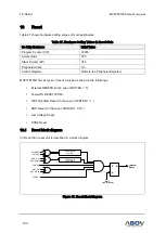
16.9
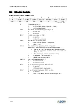
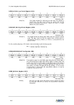
I2C register description
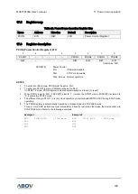
I2CMR (I2C Mode Control Register): DAH
7
6
5
4
3
2
1
0
IIF
IICEN
RESET
INTEN
ACKEN
MASTER
STOP
START
R/W
R/W
R/W
R/W
R/W
R
R/W
R/W
Initial value: 00H
IIF
This is interrupt flag bit.
0
No interrupt is generated or interrupt is cleared
1
An interrupt is generated
IICEN
Enable I2C Function Block (by providing clock)
0
I2C is inactive
1
I2C is active
RESET
Initialize internal registers of I2C.
0
No operation
1
Initialize I2C, auto cleared
INTEN
Enable interrupt generation of I2C.
0
Disable interrupt, operates in polling mode
1
Enable interrupt
ACKEN
Controls ACK signal generation at ninth SCL period.
NOTE
: ACK signal is output (SDA=0) for the following 3 cases.
When received address packet equals to SLA bits in I2CSAR
When received address packet equals to value 0x00 with
GCALL enabled
When I2C operates as a receiver (master or slave)
0
No ACK signal is generated (SDA=1)
1
ACK signal is generated (SDA=0)
MASTER
Represent operating mode of I2C
0
I2C is in slave mode
1
I2C is in master mode
STOP
When I2C is master, generates STOP condition.
0
No operation
1
STOP condition is to be generated
START
When I2C is master, generates START condition.
0
No operation
1
START or repeated START condition is to be generated