


11. PPG (Programmable Pulse Generator)
MC97F6108A User’s manual
104
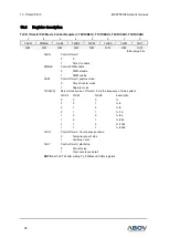
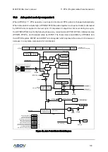
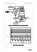
11.8.1
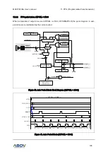
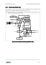
PPG period decrease
When comparator 2 outputs high, ATPHR/ATPLR (the period register in auto period mode) is decreased
by DSTEP and it is applied to the next cycle.
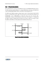
NOTE:
In duty state, comparator2 is not detected.
{PPGH, PPGL}
(16-bit Counter)
ATPRL
(8-bit)
0 1
MUX
- DSTEP[7:0]
00 01 10 11
MUX
CPOUT2
(in the previous period)
current period
+ USTEP[7:0]
increase
decrease
ATPSEL[1:0]
ATPEN
0 1
MUX
PPGPL
(8-bit)
PPG start
read only
PPG period register
PERIOD write
M 0
U
X 1
M 0
U
X 1
ATPMAXHR
(8-bit)
ATP_MAX
ATPEN
~(PERIOD write)
M
A
X
m
a
tc
h
M
IN
m
a
tc
h
current period
current period
ATPEN
PPGPH
(8-bit)
ATPMAXHR
(8-bit)
ATPMINHR
(8-bit)
ATPMINHR
(8-bit)
ATPRH
(8-bit)
period matching
CMP2
C2DBSEL[1:0]
by pass
0.3 us
0.6 us
1.2 us
ATP_MIN
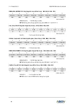
Figure 43. Period Decrement Block Diagram in Auto Period Mode
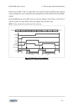
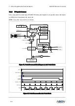
PPGO
ATPHR, ATPLR
start pulse
1
A
CPOUT2
DSTEP
9
PPGPH/PPGPL
A
8
7
6
5
PERIOD=A
PERIOD=A
PERIOD=9
PERIOD=8
PERIOD=7
PERIOD=6
PERIOD=5
ATPEN
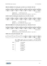
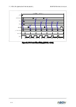
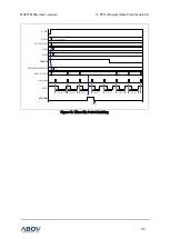
Figure 44. Period Decrement in Auto Period Mode