


MC97F6108A User’s manual
11. PPG (Programmable Pulse Generator)
103
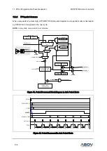
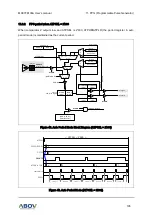
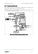
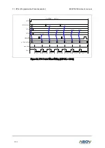
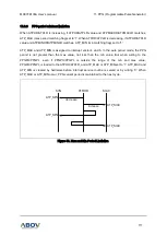
11.8
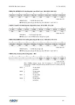
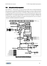
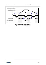
Auto period mode by comparator 2
When ATPEN is '1', PPG operates in auto period mode and PPG period is changed automatically.
When comparator 2 outputs high, ATPHR/ATPLR (the period register in auto period mode) is decreased
by DSTEP and it is applied to the next cycle. If comparator 2 output does not occur during one cycle,
the ATPHR/ATPLR is set to the following three value, current value (ATPHR, ATPLR), initially set value
(PPGPH, PPGPL), and increased value by USTEP. The three value is selectable by ATPSEL[1:0] in
the ATPCR register. DSTEP and USTEP is 8-bit register which represent the amount of increase or
decrease. In duty state, comparator2 is not detected.
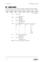
ATPCR
ADDRESS : F9
H
INITIAL VALUE : 0000_0000
b
MAX_REQ
MIN_REQ
ATPMAX
ATPMIN
-
ATPSEL[1:0]
ATPEN
{PPGH, PPGL}
(16-bit Counter)
PPGST
PPGIF
PPG Interrupt
clear & start
S
R
Q
clear
PPG_PE
PPGO
C0_FLAG
PPGMD
clear
PPG_CLK
ATPRL
(8-bit)
0 1
MUX
- DSTEP[7:0]
00 01 10 11
MUX
CPOUT2
(in the previous period)
current period
+ USTEP[7:0]
increase
decrease
ATPSEL[1:0]
ATPEN
0 1
MUX
PPGPL
(8-bit)
PPG start
read only
PPG period register
PERIOD write
M 0
U
X 1
M 0
U
X 1
ATPMAXHR
(8-bit)
ATP_MAX
ATPEN
~(PERIOD write)
M
A
X
m
a
tc
h
M
IN
m
a
tc
h
current period
current period
ATPEN
PPGPH
(8-bit)
ATPMAXHR
(8-bit)
ATPMINHR
(8-bit)
ATPMINHR
(8-bit)
ATPRH
(8-bit)
E7
H
E6
H
F9
H
F1
H
E9
H
C1
H
C9
H
2F04
H
2F05
H
2F06
H
2F07
H
PPGPH
PPGPL
ATPCR
ATPHR
ATPLR
USTEP
DSTEP
ATPMAXLR
ATPMAXHR
ATPMINLR
ATPMINHR
PPG period register high
PPG period register low
ATP mode control register
ATP mode period high register
ATP mode period low register
ATP mode up step register
ATP mode down step register
ATP mode max period low register
ATP mode max period high register
ATP mode min period low register
ATP mode min period high register
duty matching
period matching
CMP2
C2DBSEL[1:0]
by pass
0.3 us
0.6 us
1.2 us
ATP_MIN
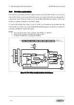
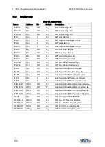
Figure 42. Auto Period Mode Block Diagram