6. I/O ports
A96G140/A96G148/A96A148 User’s manual
52
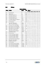
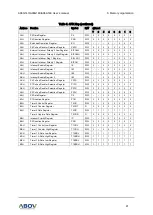
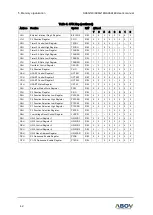
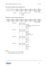
P0FSRL (Port 0 Function Selection Low Register): D2H
7
6
5
4
3
2
1
0
P0FSRL7
P0FSRL6
P0FSRL5
P0FSRL4
P0FSRL3
P0FSRL2
P0FSRL1
P0FSRL0
R/W
R/W
R/W
R/W
R/W
R/W
R/W
R/W
Initial value: 00H
P0FSRL[7:6]
P03 Function Select
P0FSRL7 P0FSRL6 Description
0
0
I/O Port(EINT1 function possible when input)
0
1
reserved
1
0
AN1 Function
1
1
reserved
P0FSRL[5:4]
P02 Function Select
P0FSRL5 P0FSRL4 Description
0
0
I/O Port(EINT0 function possible when input)
0
1
AVREF Function
1
0
AN0 Function
1
1
T4O/PWM4O Function
P0FSRL[3:2]
P01 Function Select
P0FSRL3 P0FSRL2 Description
0
0
I/O Port
0
1
T3O/PWM3O Function
1
0
reserved
1
1
TXD2 Function
P0FSRL[1:0]
P00 Function Select
P0FSRL1 P0FSRL0 Description
0
0
I/O Port(EC3 function possible when input)
0
1
reserved
1
0
reserved
1
1
RXD2 Function
6.3
P1 port
6.3.1
P1 port description
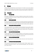
P1 is an 8-bit I/O port. P1 control registers consist of P1 data register (P1), P1 direction register (P1IO),
debounce enable register (P15DB), P1 pull-up resistor selection register (P1PU), andP1 open-drain
selection register (P1OD). Refer to the port function selection registers for the P1 function selection.
6.3.2
Register description for P1


