3-22
Chapter 3
3-7. PnP/PCI
Configurations
This section describes configuring the PCI bus system. PCI, or
P
ersonal
C
omputer
I
nterconnect, is a
system which allows I/O devices to operate at speeds nearing the speed the CPU itself uses when
communicating with its own special components. This section covers some very technical items and it is
strongly recommended that only experienced users should make any changes to the default settings.
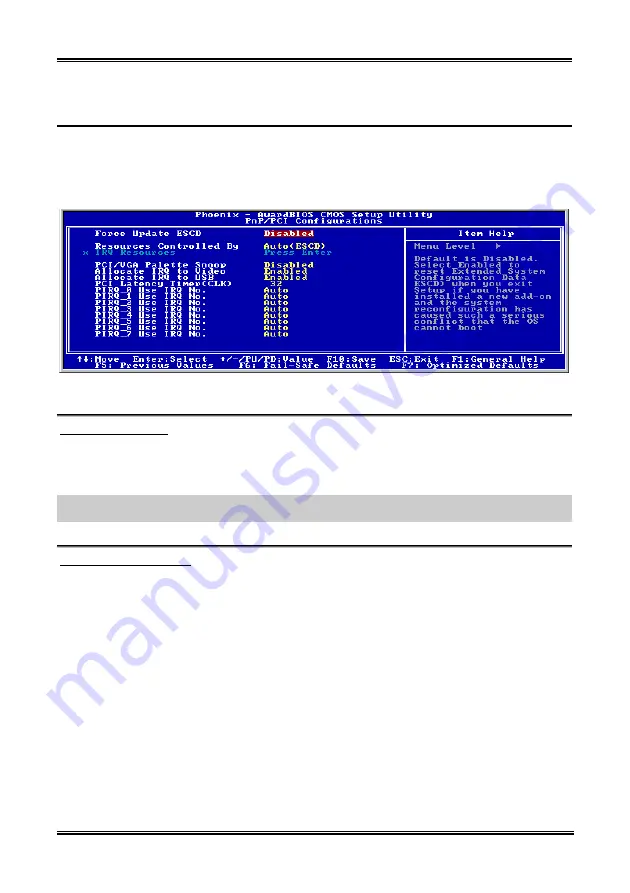
Figure 3-9. PnP/PCI Configurations Setup Screen Shot
Force Update ESCD:
If you want to clear ESCD data next time you boot up, and ask the BIOS to reset the settings for the Plug
& Play ISA Card and the PCI Card, select Enabled. But the next time you boot up, this option will
automatically be set as Disabled.
NOTE:
The ESCD (Extended System Configuration Data) contains the IRQ, DMA, I/O port, memory
information of the system. This is a specification and a feature specific to the Plug & Play BIOS.
Resources Controlled By:
Two options are available: Auto(ESCD) and Manual. Default setting is
Auto(ESCD)
. When the setting is
Auto(ESCD), the
IRQ Resources
and
Memory Resources
can not be changed. When resources are
controlled manually, the
IRQ Resources
and
Memory Resources
can then be changed.
PCI
PnP
devices compliant with the Plug and Play standard, whether designed for the PCI bus
architecture.
The Award Plug and Play BIOS has the capability to automatically configure all of the boot and Plug and
Play compatible devices. If you select
Auto (ESCD)
, The IRQ Resources item will be disabled, as the
BIOS automatically assigns them. But if you have trouble in assigning the interrupt resources
automatically, you can select
Manual
to set which IRQ is assigned to PCI PnP cards.
Figure 3-10 shows you the screen of IRQ resources. Each item has two options: PCI Device and Reserved.
The default setting is
PCI Device
.
BE7 Series
Содержание BE7
Страница 1: ...BE7 Series BE7 G BE7 S BE7 RAID BE7 B BE7 Socket 478 System Board User s Manual 4200 0329 02 Rev 1 00 ...
Страница 19: ...Introduction 1 3 1 2 Layout Diagram BE7 G User s Manual ...
Страница 20: ...1 4 Chapter 1 1 3 Layout Diagram BE7 S BE7 Series ...
Страница 21: ...Introduction 1 5 1 4 Layout Diagram BE7 RAID User s Manual ...
Страница 22: ...1 6 Chapter 1 1 5 Layout Diagram BE7 B BE7 Series ...
Страница 23: ...Introduction 1 7 1 6 Layout Diagram BE7 User s Manual ...
Страница 24: ...1 8 Chapter 1 1 8 Chapter 1 BE7 Series BE7 Series ...
Страница 39: ...Hardware Setup 2 15 13 IDE1 IDE2 and IDE3 IDE4 Connectors User s Manual ...
Страница 72: ...A 2 Appendix A A 2 Appendix A BE7 Series BE7 Series ...
Страница 74: ...B 2 Appendix B 5 Choose Yes I want to restart my computer now and click Finish to complete setup BE7 Series ...
Страница 84: ...E 2 Appendix E BE7 Series ...
Страница 86: ...F 2 Appendix F F 2 Appendix F BE7 Series BE7 Series ...
Страница 112: ...L 6 Appendix L Thank You ABIT Computer Corporation http www abit com tw BE7 Series ...


