manualshive.com logo in svg
background image

T E C H N O L O G Y

F O R

T H E

W E L D E R ´ S

W O R L D .

www.binzel-abicor.com
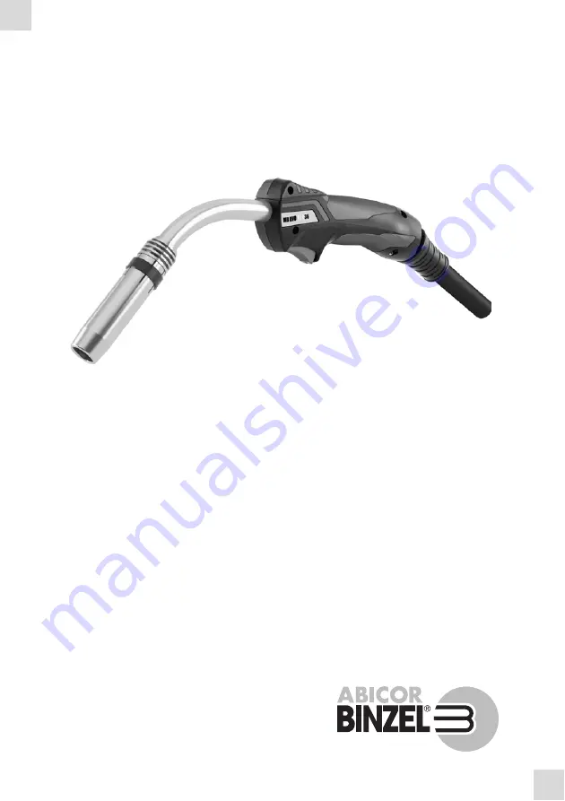
MB EVO PRO/MB EVO

DE

Betriebsanleitung

 / EN

Operating instructions

FR

Mode d’emploi

 / ES

Instructivo de servicio

DE

MIG/MAG Schweißbrenner

EN

MIG/MAG Welding torch 

FR

MIG/MAG Torches de Soudage 

ES

MIG/MAG Antorcha de soldadura 

Содержание MB EVO PRO Series

Страница 1: ...R L D www binzel abicor com MB EVO PRO MB EVO DE Betriebsanleitung EN Operating instructions FR Mode d emploi ES Instructivo de servicio DE MIG MAG Schwei brenner EN MIG MAG Welding torch FR MIG MAG T...

Страница 2: ...weltweit entnehmen Sie bitte unserer Homepage www binzel abicor com 1 Identifikation DE 3 1 1 Kennzeichnung DE 3 2 Sicherheit DE 3 2 1 Bestimmungsgem e Verwendung DE 3 2 2 Klassifizierung der Warnhin...

Страница 3: ...rfen nur mit Original ABICOR BINZEL Ersatzteilen betrieben werden In den folgenden Abbildungen werden die Schwei brenner in der Ausf hrung MB EVO PRO 501 D dargestellt 1 1 Kennzeichnung Das Produkt er...

Страница 4: ...Gaszufuhr Weitere Ma nahmen entnehmen Sie der Betriebsanleitung Stromquelle oder der Dokumentation weiterer Peripherieger te GEFAHR Bezeichnet eine unmittelbar drohende Gefahr Wenn sie nicht gemieden...

Страница 5: ...Umgebungsbedingungen im Betrieb Spannungsart DC Polung der Elektroden bei DC in der Regel positiv Schutzgas DIN EN ISO 14175 CO2 und Mischgas M21 Drahtarten handels bliche Runddr hte Spannungsbemessu...

Страница 6: ...g Belastung CO2 M21 CO2 M21 A A A A mm l min Tab 3 Produktspezifische Brennerdaten EN 60 974 7 Vorlauftemp max 40 C Durchfluss min 1 5 l min Flie druck min 2 5 bar max 3 5 bar Tab 4 Angaben zur K hlun...

Страница 7: ...letzungsgefahr und Ger tesch den durch unautorisierte Personen Unsachgem e Reparaturen und nderungen am Produkt k nnen zu erheblichen Verletzungen und Ger tesch den f hren Die Produktgarantie erlischt...

Страница 8: ...r folgenden Abbildungen durch 1 Legen Sie das Schlauchpaket gestreckt aus Abb 1 Schlauchpaket gestreckt auslegen A B C Abb 2 F hrungsspirale k rzen A C B HINWEIS W Wir empfehlen Ihnen die F hrungsspir...

Страница 9: ...wurfmutter mit dem Mehrfachschl ssel handfest an Abb 4 Brennerhals ausr sten A B C D HINWEIS Bei Kunststoffseelen mit Aussendurchmesser 4 00 mm muss das Kapillarrohr im Zwischenanschluss durch ein F h...

Страница 10: ...MB EVO PRO MB EVO Abb 6 Kunststoffseele anspitzen A B C 40 HINWEIS Schieben Sie die Kunststoffseele durch den Drahtf rderschlauch bis zum sp rbaren Anschlag in die Stromd se Abb 7 Kunststoffseele sich...

Страница 11: ...ineralisiertes Wasser als K hlmittel oder f r Dichtheits und Durchflusspr fungen Dies kann die Lebensdauer Ihres Schwei brenners beeintr chtigen Wir empfehlen f r fl ssiggek hlte Schwei brenner die Ve...

Страница 12: ...h ngt von der Schwei aufgabe und der Gasd sengeometrie ab Stellen Sie alle Schutzgasverbindungen gasdicht her Um eine Verstopfung durch Verunreinigung in der Schutzgasversorgung zu verhindern m ssen S...

Страница 13: ...i start 2 Taster l sen Schwei ende 6 Betrieb 1 Schutzgasflasche ffnen Stromquelle einschalten 2 Schwei parameter einstellen 3 Schwei start 7 Au erbetriebnahme 1 Schwei ende 2 Schutzgas Nachstr mzeit a...

Страница 14: ...und r cklaufes Sperren Sie die Druckluftzufuhr ab Trennen Sie alle elektrischen Verbindungen WARNUNG Verbrennungsgefahr Die Schwei brenner werden w hrend des Schwei vorgangs stark erhitzt Lassen Sie...

Страница 15: ...n Bestellunterlagen Kontakt f r Beratung und Bestellung finden Sie im Internet unter www binzel abicor com Verwenden Sie zur Montage und Demontage der Verschlei teile den ABICOR BINZEL Mehrfachschl ss...

Страница 16: ...DE 16 BAL 0414 0 2018 08 01 8 Wartung und Reinigung MB EVO PRO MB EVO 1 Gasd se 2 Gasverteiler 3 Stromd se 4 D senstock 5 Brennerhals Abb 13 Typ 401D 501D 401 501 Typ 401 501 Typ 401D 501D 1 2 3 4 5...

Страница 17: ...alle Bauteile in umgekehrter Reihenfolge 9 Entsorgung WARNUNG Verletzungsgefahr Schwere Verletzung durch herumwirbelnde Teile Tragen Sie beim Ausblasen der Drahtf hrung geeignete Schutzkleidung insbes...

Страница 18: ...ZEL national subsidiaries and partners worldwide can be found on our website at www binzel abicor com 1 Identification EN 3 1 1 Marking EN 3 2 Safety EN 3 2 1 Designated use EN 3 2 2 Classification of...

Страница 19: ...he market to which it has been introduced A corresponding marking has been affixed to the product if required 2 Safety The enclosed safety instructions must be observed 2 1 Designated use The device d...

Страница 20: ...sult in slight or minor injuries NOTICE Describes the risk of impairing work results or potential material damage to the equipment WARNING Hazards caused by improper use If improperly used the device...

Страница 21: ...50 60 25 Air 230 200 230 200 60 0 8 1 2 10 18 24 Air 250 220 250 220 60 0 8 1 2 10 18 26 Air 270 240 270 240 60 0 8 1 2 10 18 36 Air 320 290 320 290 60 0 8 1 2 10 20 240 D Liquid 325 300 300 270 100 0...

Страница 22: ...n succession DANGER Risk of injury due to unexpected start up The following instructions must be adhered to for the entire duration of maintenance servicing disassembly and repair work Switch off the...

Страница 23: ...NOTICE Select the proper wire type and the related wire guide for your application Use insulated liners or PA liners only New still unused spiral liners or PA liners have to be shortened to the actual...

Страница 24: ...angle of 40 and deburr the edge before mounting Fig 3 Removing and deburring the liner A B 3 40 NOTICE W Tightly screw on the nut hand tight using the switch key wrench Fig 4 Equipping the torch neck...

Страница 25: ...below Fig 5 Removing the nut A NOTICE W We recommend that you sharpen the PA liner to an angle of 40 before assembly using the ABICOR BINZEL sharpener Fig 6 Sharpening the PA liner A B C 40 NOTICE Sli...

Страница 26: ...8 01 4 Putting into operation MB EVO PRO MB EVO 4 2 Connecting the cable assembly 1 Mount the shielding gas and control lead connectors correctly Fig 8 Shortening the PA liner B A C Fig 9 Connecting t...

Страница 27: ...t be purged of any air each time the device is commissioned and after every cable assembly change disconnect the coolant return hose from the coolant recirculator and hold it over a collection recepta...

Страница 28: ...ng gas cylinder and switch on the power source 2 Set the welding parameters 3 Start welding 7 Putting out of operation 1 Stop welding 2 Wait until the shielding gas post flow time has passed and then...

Страница 29: ...NG Risk of burns The welding torches are heated to a very high temperature during welding Allow the welding torches to cool down Wear the correct protective gloves if necessary NOTICE Maintenance and...

Страница 30: ...3 Gas nozzle holder 4 Tip adaptor 5 Retaining spring 6 Torch neck Fig 11 Type 15 25 Type 25 Type 15 1 2 4 6 5 3 1 Gas nozzle 2 Contact tip 3 Tip adaptor 4 Gas diffuser 5 Torch neck Fig 12 Type 24 26...

Страница 31: ...all parts in the reverse sequence 9 Disposal WARNING Risk of injury Serious injuries can be caused by parts swirling around When cleaning the wire guide with compressed air wear suitable protective cl...

Страница 32: ...es partenaires d ABICOR BINZEL dans le monde sur la page d accueil www binzel abicor com 1 Identification FR 3 1 1 Marquage FR 3 2 S curit FR 3 2 1 Utilisation conforme aux dispositionsFR 3 2 2 Classi...

Страница 33: ...MAG ne doivent tre exploit es qu avec des pi ces de rechange ABICOR BINZEL d origine Les illustrations suivantes pr sentent les torches de soudage de la version MB EVO PRO 501 D 1 1 Marquage Le produ...

Страница 34: ...ctrique Alimentation en air comprim Alimentation en liquide de refroidissement Alimentation en gaz D autres mesures prendre sont d crites dans le mode d emploi Source de courant ou dans la documentati...

Страница 35: ...TRBS 1203 Transport et stockage 25 C 55 C Humidit relative de l air Jusqu 90 20 C Tab 1 Temp rature de l air ambiant Type de tension CC Polarit des lectrodes pour CC G n ralement positive Gaz de prote...

Страница 36: ...pacit CO2 M21 CO2 M21 A A A A mm l min Tab 3 Caract ristiques sp cifiques EN 60 974 7 Temp rature de d part max 40 C D bit min 1 5 l min Pression d coulement min 2 5 bar max 3 5 bar Tab 4 Temp rature...

Страница 37: ...n en gaz Coupez l alimentation en liquide de refroidissement Coupez l alimentation en air comprim D branchez tous les raccordements lectriques DANGER Risque de blessures et d endommagement de l appare...

Страница 38: ...rect et l amen e de fil correspondante pour votre application N utilisez que des gaines guide fil isol es ou synth tiques Les gaines guide fil synth tiques ou non neuves et non utilis es doivent tre r...

Страница 39: ...f ter la gaine guide fil un angle de 40 et de l bavurer avant l assemblage Fig 3 Retirer et bavurer la gaine guide fil A B 3 40 AVIS W Vissez bien l crou d accouplement l aide de la cl universelle Fig...

Страница 40: ...aff ter la gaine guide fil synth tique un angle de 40 avant l assemblage avec le taille gaine ABICOR BINZEL Fig 6 Aff ter la gaine guide fil synth tique A B C 40 AVIS Introduisez la gaine guide fil sy...

Страница 41: ...B EVO 4 Mise en service 4 2 Raccordement du faisceau 1 Assemblez le raccordement de gaz de protection et le connecteur du c ble de commande correctement Fig 8 Raccourcir la gaine guide fil synth tique...

Страница 42: ...ez ce sujet la fiche de donn es de s curit correspondante Lors d une premi re installation et apr s chaque changement de faisceau le circuit de refroidissement doit tre purg desserrez le tuyau de reto...

Страница 43: ...e de courant respective et doivent tre command s s par ment 5 1 Fonction en 2 temps de la g chette 1 G chette de la poign e maintenue enfonc e lancement du processus de soudage 2 Rel chement de la g c...

Страница 44: ...sez fonctionner le refroidisseur pendant env 5 min apr s le soudage DANGER Risque de blessure en cas de d marrage inattendu Pendant toute la dur e des travaux d entretien d installation de d montage e...

Страница 45: ...s et remplacez les si n cessaire Lors des travaux d entretien et de nettoyage portez toujours votre quipement de protection individuel AVIS Les caract ristiques et r f rences des pi ces d quipement pi...

Страница 46: ...3 4 5 1 Buse gaz 2 Diffuseur de gaz 3 Tube contact 4 Support tube contact 5 Col de cygne Fig 13 Type 401D 501D 401 501 Type 401 501 Type 401D 501D 1 2 3 4 5 AVERTISSEMENT Risque de blessure Risque de...

Страница 47: ...e faisceau et tendez le 2 Soufflez le c ble transport de fil des deux c t s 3 Assemblez tous les composants dans l ordre inverse 9 limination Fig 14 quiper le col de cygne C D F E A B AVIS N liminez p...

Страница 48: ...y socios de ABICOR BINZEL en todo el mundo consulte nuestra p gina de inicio en www binzel abicor com 1 Identificaci n ES 3 1 1 Etiquetado ES 3 2 Seguridad ES 3 2 1 Utilizaci n conforme a lo prescrit...

Страница 49: ...e exclusivamente con piezas de recambio originales ABICOR BINZEL En las siguientes ilustraciones se representan las antorchas de soldadura en la versi n MB EVO PRO 501 D 1 1 Etiquetado El producto sat...

Страница 50: ...istro de aire comprimido Suministro de refrigerante Suministro de gas Para m s medidas v ase el manual de instrucciones Fuente de corriente o la documentaci n de otros aparatos perif ricos PELIGRO Ind...

Страница 51: ...aparato debe ser utilizado exclusivamente por personal capacitado en Alemania consulte la normativa TRBS 1203 Transporte y almacenamiento De 25 C a 55 C Humedad relativa del aire Hasta 90 a 20 C Tab...

Страница 52: ...6 10 20 401 l quido 475 425 450 400 100 0 8 1 6 10 20 501 D l quido 550 500 500 450 100 1 0 1 6 10 20 501 aire 575 525 550 500 100 1 0 1 6 10 20 Tab 3 Datos espec ficos de la antorcha EN 60 974 7 Temp...

Страница 53: ...esiones y da os en el aparato por personas no autorizadas Las reparaciones y modificaciones indebidas en el producto pueden causar lesiones graves y da os en el aparato La garant a del producto se anu...

Страница 54: ...e a las siguientes ilustraciones 1 Coloque el ensamble de cables de forma estirada Fig 1 Colocaci n del ensamble de cables de forma estirada A B C Fig 2 Recorte de la gu a A C B AVISO W Antes del mont...

Страница 55: ...tuerca de uni n con la llave m ltiple Fig 4 Equipamiento del cuello de antorcha A B C D AVISO En caso de gu as pl sticas con un di metro exterior de 4 mm el tubo capilar del adaptador de distancia de...

Страница 56: ...EVO Fig 6 Afilado de la gu a pl stica A B C 40 AVISO Deslice la gu a pl stica por el conductor para gu a de alambre hasta que haga tope de forma perceptible con la punta de contacto Fig 7 Fijaci n de...

Страница 57: ...alizada como refrigerante o para pruebas de estanqueidad y pruebas de flujo Esto puede mermar la vida til de la antorcha de soldadura Recomendamos el uso de un refrigerante de la serie BTC de ABICOR B...

Страница 58: ...or separado AVISO El tipo y la cantidad de gas de protecci n que se utilizar n dependen del proceso de soldadura y de la geometr a de la tobera de gas Todas las conexiones para el gas de protecci n de...

Страница 59: ...3 Inicio del proceso de soldadura 7 Puesta fuera de servicio 1 Final del proceso de soldadura 2 Espere a que termine el flujo posterior del gas de protecci n y desconecte la fuente de corriente 3 Cier...

Страница 60: ...stro de aire comprimido Desconecte todas las conexiones el ctricas ADVERTENCIA Riesgo de quemaduras Las antorchas de soldadura alcanzan temperaturas muy elevadas durante el proceso de soldadura Deje q...

Страница 61: ...alizadas de piezas de recambio y de desgaste de ABICOR BINZEL www binzel abicor com Utilice la llave m ltiple ABICOR BINZEL para el montaje y el desmontaje de las piezas de desgaste y aseg rese de que...

Страница 62: ...to 4 Porta puntas 5 Cuello de antorcha Fig 13 Tipos 401D 501D 401 501 Tipos 401 501 Tipos 401D 501D 1 2 3 4 5 ADVERTENCIA Riesgo de lesiones Lesiones graves debido a piezas proyectadas Utilice ropa de...

Страница 63: ...quelo de forma estirada 2 Limpie el conductor para gu a de alambre desde ambos lados con aire comprimido 3 Monte todos los componentes siguiendo la secuencia inversa 9 Eliminaci n Fig 14 Equipamiento...

Страница 64: ...R T H E W E L D E R S W O R L D www binzel abicor com BAL 0414 0 2018 08 01 Alexander Binzel Schweisstechnik GmbH Co KG Postfach 10 01 53 D 35331 Giessen Tel 49 0 64 08 59 0 Fax 49 0 64 08 59 191 Emai...

Отзывы: