EN
-
14
4 Product description
iROB
®
501, iROB
®
401, iROB
®
301
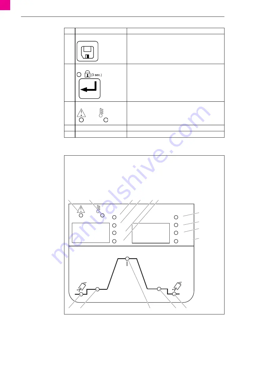
The LEDs on the control panel have the following meanings:
Y
<Save> button
Saves the set parameters in the job memory.
7.6 Managing the job memory on page EN
Z
<Enter> button
Performs the administrative functions such as button lock,
password, and assignment of welding parameters to memory
locations.
If the button is pressed for 3 seconds or more, button lock is
activated.
AA
<Warning/temperature> LED
The LED illuminates or blinks as soon as an error occurs or if the
device overheats.
10 Faults and troubleshooting on page EN
AB
USB port
Data can be read from or stored to a USB memory via the port.
AC
Input for service
The interface is used exclusively for service purposes.
Fig. 8
LED overview
A
Warning LED
B
LED for temperature
C
LED for amperes
D
LED for wire feed speed
E
LED for time
F
LED for pulse frequency
G
LED for volts
H
LED for arc length and/or voltage correction
I
LED ratio of upper/lower value of wire feed speed
for
iArc
mX Move DC
J
Job No. LED
K
LED for gas post-flows (shielding gas)
L
LED for end crater filling parameter
M
LED for main welding parameter
N
LED for start welding parameter
O
LED for gas pre-flows (shielding gas)
Tab. 1
Control elements
Pos. Name
Function
A
m/min
sec
Hz
±
V
IE
IS
%
Job-No.
O
A
N
L
K
B
M
C
D
E F
G
H
I
J
Содержание iROB 301
Страница 81: ...iROB 501 iROB 401 iROB 301 Notizen DE 81 Notizen...
Страница 158: ...EN 78 Notes iROB 501 iROB 401 iROB 301 Notes...
Страница 159: ...iROB 501 iROB 401 iROB 301 Notes EN 79 Notes...


