


Page 4
–18
2104349 rev. AD
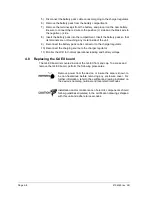
7) If the user is able to do so at this point, remove the external power that is
feeding the unit. If this can be done, skip to step 10; otherwise, continue to
the next step.
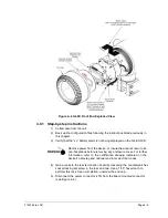
Figure 4
–11 G4 EX with block manifold
Remove power from the device, or insure the area is known to be
non-hazardous before removing any enclosure cover. For further
information, refer to the certification drawing indicated on the
device’s nametag and national and local electrical codes.
8) Gain access to the rear termination board by loosening the countersunk hex
socket locking set screw in the rear end cap. Use a 1/16” hex wrench to
perform this task. Upon completion, unscrew the end cap.
9) Disconnect the power connection (J16) from the termination board mounted
connector.
Remove power from the device, or insure the area is known to be
non-hazardous before removing any enclosure cover. For further
information, refer to the certification drawing indicated on the
device’s nametag and national and local electrical codes.
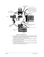
+
-
HIGH SIDE
EQUALIZER VALVE
LOW SIDE
EQUALIZER VALVE
VENT TO
ATMOSPHERE
XFC
G4
EX
Содержание XSeries G4 6200
Страница 41: ...2104349 rev AD Page 1 27 Figure 1 22 Ethernet communication cable Figure 1 23 Ethernet connectivity diagram ...
Страница 42: ......
Страница 61: ...2104349 rev AD Page 2 19 Figure 2 18 G4 EX to UPS ...
Страница 62: ......
Страница 130: ......
Страница 163: ...2104349 rev AD Page 33 ...