


Page 4
–16
2104349 rev. AD
4.11 Replacing the lithium battery
Do not remove power to the unit. Loss of power to the unit
will initiate a cold start. All data and configuration files will be
lost.
4.11.1 Step-by-step instructions
1) Collect data from the unit.
2) Back up the configuration files following the instructions listed previously in
this chapter.
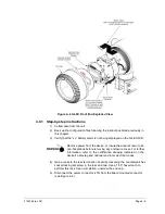
3) Gain access to the G4 EX board by loosening the countersunk hex socket
locking set screw in the front end cap. Use a 1/16” hex wrench to perform
this task. When completed, unscrew the end cap.
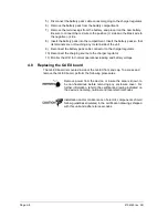
Remove power from the device, or insure the area is known to be
non-hazardous before removing any enclosure cover. For further
information, refer to the certification drawing indicated on the
device’s nametag and national and local electrical codes.
4) After the end cap has been removed, gently pull the graphic overlay plate
away from the snap on standoffs.
5) Upon completion, gently remove the lithium battery connector (J5) from the
G4 EX board.
6) Once the lithium battery connector is removed, snap the board out of the
device. Please note that the board is still connected to device through the
cables in the back.
7) After the G4 EX board has partially been removed, unplug the sensor
connector cable (J6) and the ribbon cable (J1) from the G4 EX board. This
will allow the board to be completely removed from the device.
8) The user will now see a manufacturing plate. The lithium battery assembly
is located on the back of this plate in a small battery enclosure. Carefully
remove the plate from the snap on standoffs.
9) The lithium battery assembly is attached to the manufacturing plate by a
Velcro strip. Gently remove the lithium battery from the Velcro strip.
10) Take the new lithium battery, and attach the Velcro edge of the battery to
the Velcro strip in the battery enclosure on the manufacturing plate.
11) Once the lithium battery is attached to the manufacturing plate, snap the
plate back into the device using the appropriate standoffs.
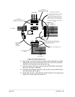
12) Take the G4 EX board, and attach the sensor cable and the ribbon cable to
their corresponding connectors.
Please note that both sensor cable and ribbon cable pin 1
wire is red. The red edge (pin 1) of the cable should plug into
the outer most edge of the connector (pin 1).
13) Attach the lithium battery cable to its corresponding connector.
Содержание XSeries G4 6200
Страница 41: ...2104349 rev AD Page 1 27 Figure 1 22 Ethernet communication cable Figure 1 23 Ethernet connectivity diagram ...
Страница 42: ......
Страница 61: ...2104349 rev AD Page 2 19 Figure 2 18 G4 EX to UPS ...
Страница 62: ......
Страница 130: ......
Страница 163: ...2104349 rev AD Page 33 ...