


Page 4
–12
2104349 rev. AD
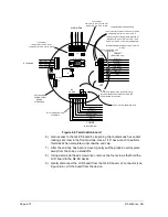
Figure 4
–7 G4 EX board Secondary Component Side.
If the user has the 2104353
–503 motherboard, they will need
to remove the processor card from the removed
motherboard and place it into the new one. This is
accomplished by pulling back the attachment brackets and
gently unsnapping the processor card from its housing.
Once completed, take the processor card and snap it into
the replacement motherboard. Continue to step 13.
13) Take the replacement G4 EX board and attach the sensor cable and the
ribbon cable to their corresponding connectors.
Please note that both the sensor cable and ribbon cable pin
1 wire are red. The red edge (pin 1) of the cable should plug
into the outer most edge of the connector (pin 1).
14) Take the lithium battery cable and attach the cable to its corresponding
connector (J5).
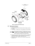
15) Align the mounting holes on the G4 EX board with the standoffs,. Once
aligned, snap the board into place within the device.
16) Once in place, line up the LCD board mounting holes to the G4 EX board.
Gently connect the LCD board into the G4 EX board via the J2 connector.
17) Take a small slot head screwdriver and attach the LCD board to the G4 EX
board using the four mounting screws.
J6
SENSOR
J1
1
13
2
14
50
2
49
1
Secondary Component Side
Sensor Connector
Содержание XSeries G4 6200
Страница 41: ...2104349 rev AD Page 1 27 Figure 1 22 Ethernet communication cable Figure 1 23 Ethernet connectivity diagram ...
Страница 42: ......
Страница 61: ...2104349 rev AD Page 2 19 Figure 2 18 G4 EX to UPS ...
Страница 62: ......
Страница 130: ......
Страница 163: ...2104349 rev AD Page 33 ...