


Page 4
–8
2104349 rev. AD
5) Disconnect the battery pack cable connector going to the charger regulator.
6) Remove the battery pack from the battery compartment.
7) Remove the terminal lugs from the battery, and place it on the new battery.
Be sure to connect the red wire to the positive (+) side and the black wire to
the negative (-) side.
8) Insert the battery pack into the compartment. Insert the battery pack so that
its terminals are not touching any metal inside of the unit.
9) Reconnect the battery pack cable connector to the charger regulator.
10) Reconnect the charging source to the charger regulator.
11) Monitor the LCD for normal operational reading and battery voltage.
4.8
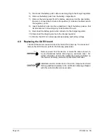
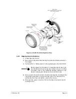
Replacing the G4 EX board
The G4 EX board is mounted inside of the G4 EX front end cap. To access and
remove the G4 EX board, perform the following procedures.
Remove power from the device, or insure the area is known to
be non-hazardous before removing any enclosure cover. For
further information, refer to the certification drawing indicated on
the device’s nametag, national and local electrical codes.
Installation and/or maintenance of electric components should
follow guidelines stipulated in the certification drawings shipped
with this unit and adhere to local codes.
Содержание XSeries G4 6200
Страница 41: ...2104349 rev AD Page 1 27 Figure 1 22 Ethernet communication cable Figure 1 23 Ethernet connectivity diagram ...
Страница 42: ......
Страница 61: ...2104349 rev AD Page 2 19 Figure 2 18 G4 EX to UPS ...
Страница 62: ......
Страница 130: ......
Страница 163: ...2104349 rev AD Page 33 ...