ABB Wireless Proximity Switches Скачать руководство пользователя страница 12

12     Planning and Installation Guidelines

Planning and
Installation Guidelines

Technical Description

Wireless Proximity Switches / Issue: 03.2005

V 6

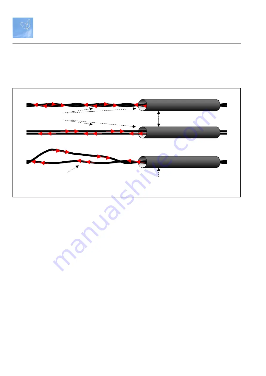
1.6 Installation of the supply line for the primary loops

The supply lines for a primary loop must be twisted with each other or held closely together in any
other way (e.g. by cable ties, heat shrinkable tubes, etc.) over the entire distance to the power
supply.

The total length of all supply lines for one pair of primary loops can be max. 8 m.

The line length required for one primary loop can be calculated as follows:
line length = circumference x number of wi 2 x supply line length.

Due to double insulation the supply lines can also be laid open.

For higher stability the supply lines for a primary loop (twisted with each other or held closely
together in any other way) can be laid in armored plastic or steel conduits or similar materials.

Fig. 1.8:  Laying of the supply lines for a primary loop

2CDC352020F0003.EPS

Permitted laying of the supply lines for the primary loops

Inadmissible laying of the supply lines for the primary loops

Installation conduit, cable duct or similar

Installation conduit, cable duct or similar

Содержание Wireless Proximity Switches

Страница 1: ...Wireless Proximity Switches Technical Description V6 Planning and Installation Guidelines ...

Страница 2: ...already been supplied may be made on the basis of the data diagrams and descriptions in this documentation This manual is copyrighted Any reproduction or third party use of this protected publication whether in whole or in part without the written permission of ABB STOTZ KONTAKT GmbH is forbidden Please note the following Target group This description is intended for the use of trained specialists...

Страница 3: ...es 14 2 2 Functional principle of the sensor heads 14 2 3 Switching distance of the sensor heads 14 2 4 Flush mounting and non flush mounting 17 2 5 Mutual influence 17 2 6 Communication module 18 2 7 Configuration of wireless proximity switches 19 2 8 Deleting the configuration of wireless proximity switches 19 2 9 Installation of the communication module 20 2 10 Switching Frequency and Latency 2...

Страница 4: ... Bus Integration and Data Mapping 36 3 11 WDI100 data structure at the PLC 37 3 11 1 Input data from the input module WDI100 37 3 11 2 Parameter to be downloaded to the input module WDI100 39 3 12 Commissioning of Communication 39 4 Power supply 40 4 1 Electrical connections 41 4 2 Primary loop sizes and current values 43 4 3 Power supply LED signals 45 4 4 Comissioning 46 Appenix A Checklist A1 ...

Страница 5: ...ength sc between 1 m and 6 m The following constraint has to be observed sc sa Procedure Set up 4 two dimensional primary loops 2 pairs around the part of the machine containing wireless proximity switches in a way that always the two opposite primary loops roughly have the same size and geometry Set up the primary loops rectangular to each other Max tolerance 8 Set up the lop pairs symmetrically ...

Страница 6: ...an the length of one of the edges Machine volume Primary loops sa sc da m 2 m 3 sc s a Design constraint valid for each of the two coil pairs The smallest side sa of one loop determines the distance da to the next parallel loop da 2 3 x sa Fig 1 1 Dimensioning principle for loop pairs Example Top view 3D representation 1 The smallest side sa of one loop determines the distance da to the next paral...

Страница 7: ...when installing a pair of primary loops and further primary loops arranged in parallel refer to fig 1 6 Fig 1 3 Arrangement of primary loops for machines with rectangular outline Top view 3D representation sb sa sc da da dc sa zc zc za za da da dc sb 1 The smallest side sa sc of one loop determines the distance da dc to the next parallel loop da 4 5 6 x sa sa sc sb is assumed 2 The following const...

Страница 8: ... installation does not have a fence around it to determine this distance for minimum distances please refer to the following table and fig 1 5 a black yellow line has to be attached to the floor in order to make the distance clear In this case suitable labelings have to be installed in the line of the distance The Engineering Package WEP100 0101 1SAF900091R0101 ZIP contains an example for this The...

Страница 9: ...to primary loops for persons wearing cardiac pacemakers principle representation Marking for the minimum clearance Top view 3D representation 2CDC352016F0003 EPS 1000 1200 8 0 2 800 1200 1400 10 0 1000 1400 1600 12 0 1300 1600 1800 13 0 1400 1800 2000 15 0 1600 2000 2200 16 0 1700 2200 2400 18 0 1900 2400 2600 20 0 2100 2600 2800 22 0 2300 2800 3000 24 0 2500 Short edge of the primary loop mm Curr...

Страница 10: ...ic connections the electromagnetic field induces currents which can attenuate the energy field of the primary loops In order to avoid an attenuation of the electromagnetic field the electric conductivity of those ring constructions has to be interrupted e g by inserting an isolating plastic part unless the distance to the loops or potentional sensor positions is large enough see b and fig 1 9 d In...

Страница 11: ...e primary loop cables can be laid open or in armored plastic conduits plastic cable ducts open or closed types etc The primary loop cable parts of the loop itself must not be laid in armored steel conduits or similar electrically conductive materials For the installation of the primary loops glas fibre reinforced plastic conduits may be used conveniently due to their self supporting property at la...

Страница 12: ...m The line length required for one primary loop can be calculated as follows line length circumference x number of windings 2 x supply line length Due to double insulation the supply lines can also be laid open For higher stability the supply lines for a primary loop twisted with each other or held closely together in any other way can be laid in armored plastic or steel conduits or similar materi...

Страница 13: ...ic parts If any of the ring constructions mentioned above cannot be electrically interrupted by inserting insulating plastic parts one dimension of the electromagnetic field will be attenuated as shown in fig 1 9 If wireless proximity switches shall be used in this area the second dimension of the electromagnetic field around the place of installation must not be shielded or attenuated in any othe...

Страница 14: ...or heads is their switching distance The switching distance depends on the dimensions and the electronic circuitry of the sensor head as well as on the size and chemical consistency of the actuator target The actuator can be moved in axial as well as in radial direction towards the sensitive part of the sensor head Nominal switching distance sn Like conventional inductive proximity switches the se...

Страница 15: ...switching point for an approaching actuator differs by a hysteresis from the switching point for a receding actuator The hysteresis is determined at an ambient temperature of 23 5 C and specified relative to the real switching distance Reliably switched off A sensor head is switched off reliably if the distance between the active sensor face and the measuring plate is at least three times the nomi...

Страница 16: ...ating factor which is normally smaller than 1 specifies how much the switching distance reduces if actuators made of stainless steel aluminum or copper are used 2CDC352024F0003 EPS Fig 2 2 Standardized pick up characteristic curve for inductive proximity switches Standard measuring plate axial radial Standard measuring plate Real switching distance Diameter of the active sensor face mm Switching d...

Страница 17: ...e sensor heads can be mounted in the machine in a way that they are particularly well protected against mechanical damages Compared with that the non flush mountable sensor heads have a significant higher switching distance However their plastic cap has to stand out of the metal environment as shown in the figure 2 5 Mutual influence In order to avoid mutual influences sensor heads of the same typ...

Страница 18: ... of the communication module The following tables show the various LED signals of the communication module Independent of configuration and communication the wireless proximity switch detects metal objects if powered suffi ciently by a magnetic field Sensor head damped Control Panel Status of Configuration Status of communikation On a new communication module from the factory or a not configured o...

Страница 19: ... 15 seconds its configuration is deleted WINK mode triggered from the input module When pressing the membrane switch the status of the wireless proximity switch is displayed In an operating system the WINK function is triggerd at the same time Sensor head damped Control Panel Status of Configuration Status of communikation CONFIG Pressing the membrane switch at the communication module starts the ...

Страница 20: ...st have a minimum clearance of 25 mm to primary loop cables in order not to expose them to too strong electromagnetic fields The mentioned minimum clearances only guarantee reliable energy supply if the rotating electromagnetic field can reach the wireless proximity switch in at least one direction i e if the wireless proximity switch is not shielded by metal parts or electrically conductive ring ...

Страница 21: ...inished 3rd proximity change error message Air Interface Latency 5 20 ms Overall Latency sensor head signal available at fieldbus typical 17ms 99 9 of the events 20ms max worst case 34ms for single events in case of heavy disturbance Independant of number of sensors used Min Pulsewidth for signal on fieldbus 20ms corresponds to typ switching frequency of 25 Hz worst case min switching frequency of...

Страница 22: ... in Config mode Error acknowledge 0 1 Reset of present error messages WINK 0 1 Set WINK command for a selected sensor 1 0 Terminate WINK mode for a selected sensor 3 Input module 3 1 Functions of the input module The following function2ality is offered by the input module choice between the modes o RUN Operation o CFG Configuration of wireless proximity switches o DEL Delete the configuration of w...

Страница 23: ...e terminals at the bottom side of the device 3 3 Switching on the input module The input module is switched on by supplying the supply voltage 24V to the screw type termi nals The device then performs a self test The four membrane switches have the following basic functionality or Scroll up and downward through the offered number ranges or options OK confirm a selection store and change to the nex...

Страница 24: ...If several proximity switches are incorrect then the device with the lowest number is indicated All disturbed sensors stand successively at the beginning of the internal list of the input module so that with and the display can be scrolled Error messages are acknowledged individually for each sensor with one single OK The blinking of the entire display disappears if all error messages have been ac...

Страница 25: ... switch 3 5 Passwordinquiry If a password 001 999 had been assigned to the input module then this is queried after each change out of the RUN mode before the first change of the settings of the input module can be done After 30 seconds without input the password inquiry will be left automatically RUN 017 1 12 RUN 017 1 12 Procedure Press membrane switch at communication module Communication module...

Страница 26: ...mity switches CFG ESC and OK Procedure Description Display content Operator options CFG CONFIGURATION menue display of the lowest not configured sensor number Change to CFG CONFIGURATION Change to CFG AUTO DETECT menue Change to CFG MAIN menue Change to another free sensor number or to CFG AUTO DETECT menue Change to CFG MAIN menue Change to CFG CONFIGURATION menue manually CFG 018 12 CFG CONFIG C...

Страница 27: ... Display content Operator options CFG AUTO DETECT menue CFG AUTO 12 or Change to another free sensor number Change to CFG MAIN menue Change to CFG AUTO DETECT SCAN or ESC OK CFG AUTO DETECT SCAN for the autromatic configuration of an input module Until at least one sensor has been configured NONE is displayed instead of a sensor number CFG AUTO DETECT STORE ESC Change to CFG AUTO DETECT menue OK O...

Страница 28: ...s reached also by ESC DEL 017 ERR 12 DEL 017 DEL 12 DEL 017 0 Err 12 Procedure Description Display content Operator options DEL MAIN menue for deleting configured wireless proximity switches DEL or Change to another mode except RUN Change to RUN mode Change to DEL DELETE menu or ESC OK DEL DELETE menue After uncomplete deletion sensor not deleted to factory setting but sensor number deleted from c...

Страница 29: ...ble for the integration into a field bus structure depends on the installed field bus and the already existing field bus participants FIELDBUS ADDR 102 FIELDBUS ADDR Change FB Addr Procedure Description Display content Operator options SET MAIN menue SET or Change to another mode except RUN Change to RUN mode Change to system settings or ESC OK FIELDBUS ADDR 002 or ESC OK Change to another systen ...

Страница 30: ...he not assigned input module with the same Cell ID range identification should amount to at least 50 m CELL ID 32 CELL ID Change CELL ID Procedure Description Display content Operator options SET MAIN menue SET or Change to another mode except RUN Change to RUN mode Change to system settings or ESC OK CELL ID 12 or ESC OK Change to another systen setting in the SET mode Change to SET MAIN menue Ch...

Страница 31: ...of the chosen number blinks range from 000 999 000 No password set unprotected Leave editing mode Change to the next number Confirmation of the password after the last number OK or ESC OK Change to another systen setting in the SET mode Change to SET MAIN menue Change for editing of the Cell ID OK Setting of a password for the input module For each input module a password can be set between 001 an...

Страница 32: ...factory settings OK or ESC OK This display only occurs if the actual Cell ID range identifier is not equal to 1 Change to SET MAIN menue Confirmation OK ESC OK This display only occurs if the actual field bus address is not equal to 0 Change to SET MAIN menue Confirmation OK ESC OK Change to SET MAIN menue Change for resetting to factory settings Communication modules with the same Cell ID are not...

Страница 33: ...re has to be looked up in the relevant documentation If this downloading of the configuration via the field bus should be prevented a change to local configuration can be done as described in the following CFG LOCAL FB FIELDBUS Procedure Description Display content Operator options SET MAIN menue SET or Change to another mode except RUN Change to RUN mode Change to system settings or ESC OK CFG LO...

Страница 34: ...eld bus parameters can be manually copied from this display and be entered manually into the control program see 3 11 2 05 CFG 04 DEC 04113 02 CFG 01 BIN 0010010001101110 01 CELL ID HEX 0032 Procedure Display content Operator options SET MAIN menue SET or Change to another mode except RUN Change to RUN mode Change to system settings or ESC OK FB PARAMETERS or ESC OK Change to other systen setting ...

Страница 35: ...for the antenna cable with the letter R for right handed circular polarization and or L for left handed circular polarization Both antennas are working alternating as transmitting and receiving antennas Each antenna is connected to the input module by a separate up to 5 m long coaxial cable In order to obtain as good as possible connection between the antennas and the wireless proximity switches t...

Страница 36: ...on system Fig 3 2 Example overview of WDI100 input module data structure and its integration via the FieldBusPlug PDP21 FBP into an ABB PLC 07KT98 with a PROFIBUS master BUS Master BUS Master WDI100 Configuration Software of Automation System PLC FieldBusPlug FBP Automation System PLC Termination resistor or bus continuation Data Parameters Fieldbus 24 V 0 V The WDI100 provides the proximity infor...

Страница 37: ...was set This happens if too many proximity changes occur to be transmitted correctly more than two within 20ms Example One change is transmitted which may take up to 20ms a second change during that time will be stored and processed if the first transmission has been finished successfully There is an offset of 1 between internal and external counting of the WSIX numbers Sensor 1 at the display of ...

Страница 38: ...em CFG LOCAL FB to choose which configuration is used after start up 0 the option is set to LOCAL to indicate to the PLC that the parameters that are downloaded to the WDI100 at start up will not be used The bit is also set to 0 in case the WDI100 is in SET DEL or CFG Mode to indicate the PLC that Parameters are blocked during this time This function is to prevent local changes to be overwritten b...

Страница 39: ...ommissioningofCommunication Assumption The WPS Power Supply is already commissioned compare chapter 4 4 Installation Mount Input Module WDI100 Mount antennas Install and connect antenna cables Connect Input Module to 24Vdc Plug in FieldBusPlug at WDI100 Ensure Supply of FieldBusPlug Connect communication modules WSIX100 to the sensor heads Switch on magnetic power supplies WPU100 Configurationofco...

Страница 40: ...sipation see V6 Power Supply WPU100 All power supplies of a setup and adjacent setups have to be connected one after the other by a synchronization cable For synchronization one power supply is set to master mode and all other power supplies connected via synchronization cables are set to slave mode All power supplies of one setup have to be switched on off via one switch To obtain a rotating elec...

Страница 41: ...nce of power supply LED3 red Disturbance of synchronisation Fig 4 2 WPU100 connection terminals DIL switch underneath cover plate and LEDs visible in operation 0 off open 1 on closed 2CDC352040F0003 EPS X14 X15 X10 X11 X1 X2 X3 X4 S1 S2 LED 3 1 2 1 2 1 2 1 2 3 PE N L 1 0 1 0 1234 1234 4 1 Electricalconnections All electrical connections and settings of DIL switches are under the cover plate undern...

Страница 42: ... power supplies WPU100 The 2nd PE connection at the housing has to be connected in a star type configuration to the common connection point cabinet In installations with a residual current circuit breaker a type B switch has to be used Primary loop Primary loop Primary loop 90 Master always 0 Slave 1 0 Slave 2 90 Power Supply Power Supply Power Supply control cabinet power line Fig 4 3 WPU100 wiri...

Страница 43: ... 20 22 24 24 3100 4500 1 2 1 8 10 12 13 15 16 18 20 22 24 24 4500 6000 1 1 8 10 12 13 15 16 18 20 22 24 24 0 0 8 0 0 0 1 0 0 3 1 0 0 4 1 0 0 6 1 0 0 7 1 0 0 9 1 0 0 1 2 0 0 3 2 0 0 5 2 0 0 5 2 Minimum distance for pacemaker carriers mm Current value A Short side of the primary loop mm 4 2 Primary loop sizes and current values Primary loops which are connected to the same primary supply should have...

Страница 44: ...DIL switch S2 0000 Master 0 1000 Slave 0 1100 Slave 90 All other settings are not allowed The synchronisation is set at DIL switch S2 as followed Current value A 0 off open 1 on closed 1 0 1 2 3 4 1 0 1 2 3 4 1 0 1 2 3 4 1 0 1 2 3 4 1 0 1 2 3 4 0000 0 0001 4 0010 5 0011 6 0100 8 0101 10 0110 12 0111 13 DIL switch S1 1 0 1 2 3 4 1 0 1 2 3 4 1 0 1 2 3 4 1 0 1 2 3 4 1 0 1 2 3 4 1100 22 1101 24 1110 1...

Страница 45: ...tched off no mains supply The right red LED blinks Disturbance due to one of the following Wrong setting of DIL switch S2 Master Slave Phase The right LED is red Sync error due to one of the following Cable cut short circuit wrong polarity mistaken in output connection via sync cable All devices connected via sync wire are slaves Several Masters present Explanation Recommended Action LED signal Sw...

Страница 46: ... matching the orientation in relation to the Master primary loop Choose the appropriate current value matching the size of the connected primary loop s for each power supply Connect the alarm error output with a suited alarm input of the control system Connect all power supplies of the setup so that they can be switched with one main switch Connect the external PE connections of the power supplies...

Страница 47: ...from metal objects by at min 3 cm recommended are 10 cm especially from magnetic steel objects if the steel is magnetic can be checked with a permanent magnet 1 2 3 Check details of the applications surrounding same as above metal floor walls poles belonging to other structures machines building close to the coils 1 2 4 Chose amount and placement of power supplies WPU100 Two loops can be connected...

Страница 48: ...ll cable into e g plastic tubes conduits glasfiber reinforced tubes are self supporting due to their mechanical strength keep a distance to metal objects reduces losses keep other wires separate if running parallel by at least 15cm 3 1 2 Mounting of cable ducts channel s for power supply wiring for primary loop wire going to the loop twisted grid connection 2nd PE sync wire 3 1 3 Installation of p...

Страница 49: ...gning the node address in the host software 4 2 4 In the host software select the WDI100 as the I O for that node and set I O addresses by turning on the auto address feature or manually address with the auto addressing turned off 4 3 Settings of Input Module WDI100 SET Menue 4 3 1 Set field bus address on WDI See Planning and Installation Guidelines Chapter 3 8 FIELDBUS ADDR 4 3 2 Set Cell ID set...

Страница 50: ...traße 82 Postfach 101680 69123 Heidelberg 69006 Heidelberg Germany Germany Telephone 49 6221 701 0 Telefax 49 6221 701 240 E Mail desst helpline de abb com Internet http www abb de stotz kontakt Manual No 2CDC 142 010 D0206 Issued 03 2005 ...

Отзывы: