


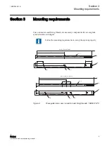


WaveGuide tube 1
WaveGuide tube 2
Z
GUID-857C161E-3F74-4EF7-9B2B-C45351AA1D10 V1 EN
Figure 5:
Horizontal displacement
3.2
Vertical displacement
The wireless communication system works properly with the vertical displacement
of Y < 5 mm between the waveguide tubes. Larger offsets are not allowed because
the transmitting power should be limited to 0 dBm.
WaveGuide tube 1
WaveGuide tube 2
Y
GUID-73057DC6-424C-473D-8A00-5DEB0BBE34A5 V1 EN
Figure 6:
Vertical displacement
3.3
Angle-related displacement
The wireless communication system works properly with the angle displacement of
< 10° between the two waveguide sections. Larger angles are not allowed because
the transmitting power should be limited to 0 dBm.
Section 3
1MRS755551 B
Mounting requirements
12
WGA631
Installation and commissioning manual
Содержание WGA631
Страница 1: ...Installation and commissioning manual Waveguide Access Point WGA631 ...
Страница 2: ......
Страница 8: ......
Страница 16: ...8 ...
Страница 22: ...14 ...
Страница 24: ...16 ...
Страница 44: ...36 ...
Страница 48: ...40 ...
Страница 50: ...42 ...
Страница 52: ...44 ...
Страница 55: ...47 ...