


14 Flame Temperature Measurement
SF910i Flame Scanner can be equipped with the pyrometer sensor (coded as IRT).
In this case, although SF910i automatically configures itself to make the IRT sensor
operating on module, it needs to set up some settings required for a correct measurement,
as well as display of flame temperature.
Note that the IRT sensor is calibrated at factory set up time and the calibration result is
downloaded into the Flame Scanner module. The result of the calibration procedure is
also stored in a file (the “Te Vector” file), where, for each sensor, its own calibration
characteristics are stored. Later, the calibration data file named with *.dat* must be
downloaded into the SF910i through the Flame Explorer tool.
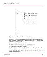
When the IRT sensor is used, the local programming facility adds automatically the new
field “TEM”, where it can configure the following flame temperature settings:
–
The flame temperature calculation average (SMO) (configurable from 10 to 60
seconds).
–
The flame temperature scale (SCA) (configurable as either Celsius or Fahrenheit).
–
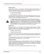
The flame temperature relay threshold (TTH). This field is meaningful when the safe
relay is set to be used as flame temperature relay (see Usage of Relay B par.). This
parameter is the threshold value above which the safe relay closes and below which
it opens. The safe LED will change from red to green when flame temperature is
above the threshold.
–
Opportunity to set new values for the
m
(MCF) and
q
(QCF) coefficients (used in
the temperature control algorithm). The default value of
m
is 1.00, and the default
value of
q
is 0.00.
8VZZ005286 B
95
14 Flame Temperature Measurement
Содержание Uvisor SF910i
Страница 1: ...Combustion Instrumentation User Manual Uvisor SF910i Integrated SafeFlame Scanner PROCESS AUTOMATION...
Страница 2: ......
Страница 6: ......
Страница 20: ...8VZZ005286 B 20...
Страница 30: ...8VZZ005286 B 30...
Страница 67: ...Figure 7 5 Version Display in Normal Mode 8VZZ005286 B 67 7 Operating Display 7 5 Version Display...
Страница 68: ...8VZZ005286 B 68...
Страница 78: ...8VZZ005286 B 78...
Страница 90: ...8VZZ005286 B 90...
Страница 92: ...8VZZ005286 B 92...
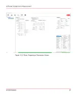
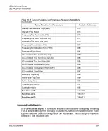
Страница 97: ...Figure 14 2 Flame Temperature Parameters Screen 8VZZ005286 B 97 14 Flame Temperature Measurement...
Страница 98: ...8VZZ005286 B 98...
Страница 108: ...8VZZ005286 B 108...
Страница 114: ...8VZZ005286 B 114...
Страница 118: ...8VZZ005286 B 118...
Страница 125: ...8 Fit in place the SF910i Flame Scanner 8VZZ005286 B 125 19 Repair and Replacement 19 2 Fiber Optic Replacement...
Страница 126: ...8VZZ005286 B 126...
Страница 128: ...8VZZ005286 B 128...
Страница 130: ...8VZZ005286 B 130...
Страница 150: ...8VZZ005286 B 150...
Страница 151: ...Appendix E Drawings 8VZZ005286 B 151 E Drawings...
Страница 152: ...Figure E 1 Enclosure Quick Release Connector and Version LOS 8VZZ005286 B 152 E Drawings...
Страница 153: ...Figure E 2 Enclosure NPT Cable Inlet and Version LOS 8VZZ005286 B 153 E Drawings...
Страница 154: ...Figure E 3 Enclosure Quick Release Connector and Version FOC 8VZZ005286 B 154 E Drawings...
Страница 155: ...Figure E 4 Enclosure NPT Cable Inlet and Version FOC 8VZZ005286 B 155 E Drawings...
Страница 156: ...Figure E 5 FOC Flexible Assembly 8VZZ005286 B 156 E Drawings...
Страница 157: ...Figure E 6 FOC Rigid Assembly 8VZZ005286 B 157 E Drawings...
Страница 160: ...Figure E 9 Bailey Flame ON Standard Replacement 8VZZ005286 B 160 E Drawings...
Страница 161: ...Figure E 10 Typical Bailey Flame ON Installation 8VZZ005286 B 161 E Drawings...
Страница 162: ...8VZZ005286 B 162...
Страница 164: ...F 1 Earth Connection Cable Figure F 1 Earth Connections 8VZZ005286 B 164 F Cables F 1 Earth Connection Cable...
Страница 170: ...8VZZ005286 B 170...
Страница 172: ...Figure G 1 Diaphragm for SF910i FOC Scanner 8VZZ005286 B 172 G Fittings G 1 TU_KIT03 Set of Diaphragms for SF910i FOC...
Страница 178: ...G 7 Counter Flange 8VZZ005286 B 178 G Fittings G 7 Counter Flange...
Страница 179: ...Figure G 7 Boiler Mounting Counter Flange for FOC Installation 8VZZ005286 B 179 G Fittings G 7 Counter Flange...
Страница 189: ......