


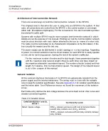


Architecture of Interconnection Network
There are several ways to build the interconnection network for the SF910i.
The simplest case is that when the user is using only one SF910i in the system. In that
case, all connections are routed from the SF910i to the control system in one single
cable path. (Exceptions might apply). For the convenience, the user must add a junction
box along the cable path.
Systems with multiple SF910i require more complex interconnection network in which
details are not the purpose of this manual. Pointing out that the communication network
must be a bus structure with each station attached to the bus by means of a short stub.
The cable must be terminated on its characteristic impedance at the first station of the
bus (usually the master) and the last one.
The power supply can be distributed in a start topology or in a bus topology. Regarding
to power, it is recommended to insert a circuit breaker for each SF910i to easily operate
on one unit for servicing purpose, leaving the rest of the system unaffected.
For the maximum number of nodes and the stub length, these parameters together
with the maximum total network length influence each other and have impact on
the maximum attainable transmission speed. The number of stubs (nodes) and their
length, for instance, limit the transmission speed. The design of the network layout
is out of the purpose of this manual.
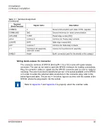
Galvanic Isolation
All the external interfaces (terminals) of the SF910i are galvanically isolated from the
power supply and the internal electronics. The wiring must be done with the suitable
care to keep the isolation specification. See also
for isolation specifications
and the below table. Error! Reference source not found for a summary of the isolation
zones.
Each table entry defines the test voltage between the zone itself and all other zones and
chassis connected together.
Table 3.3: Isolation Zones
Test Severity Levels
CAN/CSA-E60730-1 and UL
60730-1
500V
AC
between enclosure earth and all terminal blocks
(except relay contacts and +24V
DC
terminal).
Rated impulse voltage
1500V
AC
between enclosure earth and relay contacts, between
relay contacts
8VZZ005286 B
54
3 Installation
3.3 Product Installation
Содержание Uvisor SF910i
Страница 1: ...Combustion Instrumentation User Manual Uvisor SF910i Integrated SafeFlame Scanner PROCESS AUTOMATION...
Страница 2: ......
Страница 6: ......
Страница 20: ...8VZZ005286 B 20...
Страница 30: ...8VZZ005286 B 30...
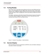
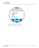
Страница 67: ...Figure 7 5 Version Display in Normal Mode 8VZZ005286 B 67 7 Operating Display 7 5 Version Display...
Страница 68: ...8VZZ005286 B 68...
Страница 78: ...8VZZ005286 B 78...
Страница 90: ...8VZZ005286 B 90...
Страница 92: ...8VZZ005286 B 92...
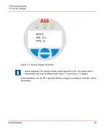
Страница 97: ...Figure 14 2 Flame Temperature Parameters Screen 8VZZ005286 B 97 14 Flame Temperature Measurement...
Страница 98: ...8VZZ005286 B 98...
Страница 108: ...8VZZ005286 B 108...
Страница 114: ...8VZZ005286 B 114...
Страница 118: ...8VZZ005286 B 118...
Страница 125: ...8 Fit in place the SF910i Flame Scanner 8VZZ005286 B 125 19 Repair and Replacement 19 2 Fiber Optic Replacement...
Страница 126: ...8VZZ005286 B 126...
Страница 128: ...8VZZ005286 B 128...
Страница 130: ...8VZZ005286 B 130...
Страница 150: ...8VZZ005286 B 150...
Страница 151: ...Appendix E Drawings 8VZZ005286 B 151 E Drawings...
Страница 152: ...Figure E 1 Enclosure Quick Release Connector and Version LOS 8VZZ005286 B 152 E Drawings...
Страница 153: ...Figure E 2 Enclosure NPT Cable Inlet and Version LOS 8VZZ005286 B 153 E Drawings...
Страница 154: ...Figure E 3 Enclosure Quick Release Connector and Version FOC 8VZZ005286 B 154 E Drawings...
Страница 155: ...Figure E 4 Enclosure NPT Cable Inlet and Version FOC 8VZZ005286 B 155 E Drawings...
Страница 156: ...Figure E 5 FOC Flexible Assembly 8VZZ005286 B 156 E Drawings...
Страница 157: ...Figure E 6 FOC Rigid Assembly 8VZZ005286 B 157 E Drawings...
Страница 160: ...Figure E 9 Bailey Flame ON Standard Replacement 8VZZ005286 B 160 E Drawings...
Страница 161: ...Figure E 10 Typical Bailey Flame ON Installation 8VZZ005286 B 161 E Drawings...
Страница 162: ...8VZZ005286 B 162...
Страница 164: ...F 1 Earth Connection Cable Figure F 1 Earth Connections 8VZZ005286 B 164 F Cables F 1 Earth Connection Cable...
Страница 170: ...8VZZ005286 B 170...
Страница 172: ...Figure G 1 Diaphragm for SF910i FOC Scanner 8VZZ005286 B 172 G Fittings G 1 TU_KIT03 Set of Diaphragms for SF910i FOC...
Страница 178: ...G 7 Counter Flange 8VZZ005286 B 178 G Fittings G 7 Counter Flange...
Страница 179: ...Figure G 7 Boiler Mounting Counter Flange for FOC Installation 8VZZ005286 B 179 G Fittings G 7 Counter Flange...
Страница 189: ......