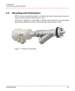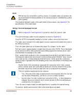
Supply generally includes all the indicated accessories, specially designed to easy the
assembly/dismantling and the aiming of the Flame Scanner.
To provide a LOS (also called direct view) installation, drill a 55 mm hole in the burner
plate according to the drilling template and fit the swivel flange basement (see
In case, a single scanner shall detect both the igniter and main flame, aim the scanner
to the primary zone of the main burner flame in a point where the pilot flame intersect
the main flame. The effect of any turbulence set by the air register must also be taken
into consideration to ensure that the pilot flame involves the targeted zone of the scanner.
Connect the air flexible hose in the ¾” provision on the “Y” union (see
SF910i - FOC (Fiber Optic Cable Installation)
The typical application of fiber optic extensions are:
–
Flexible-extended for corner fired tilting burners
–
Rigid-extended for fixed burners large wind box
The extended Flame Scanner includes both internal and external carrier. The external
extension pipe (outer carrier) may be considered a semi-permanent component of the
burner or relevant air box. Once mounted, it needs no care or maintenance.
Only the inner carrier, housed in the outer one, incorporates components that may need
maintenance and/or replacement (optic fiber lens).
Basic premises to determine the final location of the extended Flame Scanner are:
–
Define where to weld the collar in the burner bucket.
–
Make sure levers or other mechanical parts do not crunch, bang, or cut the outer
carrier inside the burner vane.
–
Test the corner tilt within the full range and make sure that the flexible extension
doesn’t bend sharply.
–
The end part of the outer carrier must be let free to slide inside the collar. The flexible
part of the extended scanner shall work as a spring keep pressing the end part into
the collar.
The extended Flame Scanner requires, in all versions, low-pressure air (preferably
supplied by booster fan). This air is used for cooling and cleaning purposes. See
specification for air requirement.
8VZZ005286 B
44
3 Installation
3.3 Product Installation
Содержание Uvisor SF910i
Страница 1: ...Combustion Instrumentation User Manual Uvisor SF910i Integrated SafeFlame Scanner PROCESS AUTOMATION...
Страница 2: ......
Страница 6: ......
Страница 20: ...8VZZ005286 B 20...
Страница 30: ...8VZZ005286 B 30...
Страница 67: ...Figure 7 5 Version Display in Normal Mode 8VZZ005286 B 67 7 Operating Display 7 5 Version Display...
Страница 68: ...8VZZ005286 B 68...
Страница 78: ...8VZZ005286 B 78...
Страница 90: ...8VZZ005286 B 90...
Страница 92: ...8VZZ005286 B 92...
Страница 97: ...Figure 14 2 Flame Temperature Parameters Screen 8VZZ005286 B 97 14 Flame Temperature Measurement...
Страница 98: ...8VZZ005286 B 98...
Страница 108: ...8VZZ005286 B 108...
Страница 114: ...8VZZ005286 B 114...
Страница 118: ...8VZZ005286 B 118...
Страница 125: ...8 Fit in place the SF910i Flame Scanner 8VZZ005286 B 125 19 Repair and Replacement 19 2 Fiber Optic Replacement...
Страница 126: ...8VZZ005286 B 126...
Страница 128: ...8VZZ005286 B 128...
Страница 130: ...8VZZ005286 B 130...
Страница 150: ...8VZZ005286 B 150...
Страница 151: ...Appendix E Drawings 8VZZ005286 B 151 E Drawings...
Страница 152: ...Figure E 1 Enclosure Quick Release Connector and Version LOS 8VZZ005286 B 152 E Drawings...
Страница 153: ...Figure E 2 Enclosure NPT Cable Inlet and Version LOS 8VZZ005286 B 153 E Drawings...
Страница 154: ...Figure E 3 Enclosure Quick Release Connector and Version FOC 8VZZ005286 B 154 E Drawings...
Страница 155: ...Figure E 4 Enclosure NPT Cable Inlet and Version FOC 8VZZ005286 B 155 E Drawings...
Страница 156: ...Figure E 5 FOC Flexible Assembly 8VZZ005286 B 156 E Drawings...
Страница 157: ...Figure E 6 FOC Rigid Assembly 8VZZ005286 B 157 E Drawings...
Страница 160: ...Figure E 9 Bailey Flame ON Standard Replacement 8VZZ005286 B 160 E Drawings...
Страница 161: ...Figure E 10 Typical Bailey Flame ON Installation 8VZZ005286 B 161 E Drawings...
Страница 162: ...8VZZ005286 B 162...
Страница 164: ...F 1 Earth Connection Cable Figure F 1 Earth Connections 8VZZ005286 B 164 F Cables F 1 Earth Connection Cable...
Страница 170: ...8VZZ005286 B 170...
Страница 172: ...Figure G 1 Diaphragm for SF910i FOC Scanner 8VZZ005286 B 172 G Fittings G 1 TU_KIT03 Set of Diaphragms for SF910i FOC...
Страница 178: ...G 7 Counter Flange 8VZZ005286 B 178 G Fittings G 7 Counter Flange...
Страница 179: ...Figure G 7 Boiler Mounting Counter Flange for FOC Installation 8VZZ005286 B 179 G Fittings G 7 Counter Flange...
Страница 189: ......


