


3.3.3
Station Address Selection
Before using the SF910i, even before beginning to configure it, the user must set the
station address.
For MODBUS, it is 34800 baud rate initially, and can be changed later by the master.
Refer to
SF910i Flame Explorer User Manual (8VZZ005308)
.
Default Initial Setting
SF910i comes from the factory already configured for MODBUS protocol, station No.1,
38400 baud.
The user can omit the protocol and station selection procedure in the following cases:
–
Installing the SF910i without using the serial communication channels.
–
Installing a point-to-point MODBUS serial channel (single or redundant) for each
SF910i. In this case, every unit will be addressed as station 1 on its own network.
This could reasonably be the case when the whole flame detection system consists
of only one or two SF910i .
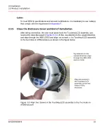
Station Address Selection Procedure
While the installation is in hazardous area, the user can set the station address operating
while the cover is not opened, touch the button through the cover glass or remotely
through Flame Explorer.
For the procedure, refer to local configuration and communication network parameters.
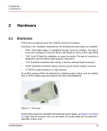
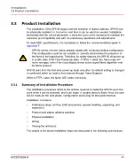
Physical Installation
SF910i Flame Scanner comply with the safety rules for installation in explosive
atmosphere except for non-ATEX versions.
Installation, removal, assembling, and disassembling procedures shall be strictly made
in accordance with the
SF910i Safety Instruction Manual (EC-DOC-G041MAN033)
.
To prevent moisture to drop into the enclosure, it is recommended to install the
SF910i with cable inlet facing down.
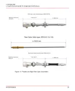
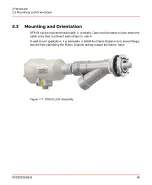
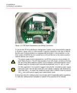
SF910i - LOS (Line Of Sight Installation)
Flame Scanner SF910i - LOS is typically supplied as part of a complete higher level
assembly as shown in
.
8VZZ005286 B
43
3 Installation
3.3 Product Installation
Содержание Uvisor SF910i
Страница 1: ...Combustion Instrumentation User Manual Uvisor SF910i Integrated SafeFlame Scanner PROCESS AUTOMATION...
Страница 2: ......
Страница 6: ......
Страница 20: ...8VZZ005286 B 20...
Страница 30: ...8VZZ005286 B 30...
Страница 67: ...Figure 7 5 Version Display in Normal Mode 8VZZ005286 B 67 7 Operating Display 7 5 Version Display...
Страница 68: ...8VZZ005286 B 68...
Страница 78: ...8VZZ005286 B 78...
Страница 90: ...8VZZ005286 B 90...
Страница 92: ...8VZZ005286 B 92...
Страница 97: ...Figure 14 2 Flame Temperature Parameters Screen 8VZZ005286 B 97 14 Flame Temperature Measurement...
Страница 98: ...8VZZ005286 B 98...
Страница 108: ...8VZZ005286 B 108...
Страница 114: ...8VZZ005286 B 114...
Страница 118: ...8VZZ005286 B 118...
Страница 125: ...8 Fit in place the SF910i Flame Scanner 8VZZ005286 B 125 19 Repair and Replacement 19 2 Fiber Optic Replacement...
Страница 126: ...8VZZ005286 B 126...
Страница 128: ...8VZZ005286 B 128...
Страница 130: ...8VZZ005286 B 130...
Страница 150: ...8VZZ005286 B 150...
Страница 151: ...Appendix E Drawings 8VZZ005286 B 151 E Drawings...
Страница 152: ...Figure E 1 Enclosure Quick Release Connector and Version LOS 8VZZ005286 B 152 E Drawings...
Страница 153: ...Figure E 2 Enclosure NPT Cable Inlet and Version LOS 8VZZ005286 B 153 E Drawings...
Страница 154: ...Figure E 3 Enclosure Quick Release Connector and Version FOC 8VZZ005286 B 154 E Drawings...
Страница 155: ...Figure E 4 Enclosure NPT Cable Inlet and Version FOC 8VZZ005286 B 155 E Drawings...
Страница 156: ...Figure E 5 FOC Flexible Assembly 8VZZ005286 B 156 E Drawings...
Страница 157: ...Figure E 6 FOC Rigid Assembly 8VZZ005286 B 157 E Drawings...
Страница 160: ...Figure E 9 Bailey Flame ON Standard Replacement 8VZZ005286 B 160 E Drawings...
Страница 161: ...Figure E 10 Typical Bailey Flame ON Installation 8VZZ005286 B 161 E Drawings...
Страница 162: ...8VZZ005286 B 162...
Страница 164: ...F 1 Earth Connection Cable Figure F 1 Earth Connections 8VZZ005286 B 164 F Cables F 1 Earth Connection Cable...
Страница 170: ...8VZZ005286 B 170...
Страница 172: ...Figure G 1 Diaphragm for SF910i FOC Scanner 8VZZ005286 B 172 G Fittings G 1 TU_KIT03 Set of Diaphragms for SF910i FOC...
Страница 178: ...G 7 Counter Flange 8VZZ005286 B 178 G Fittings G 7 Counter Flange...
Страница 179: ...Figure G 7 Boiler Mounting Counter Flange for FOC Installation 8VZZ005286 B 179 G Fittings G 7 Counter Flange...
Страница 189: ......