3.3
Product Installation
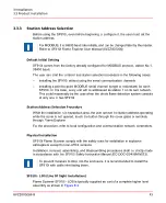
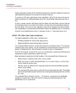
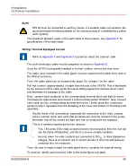
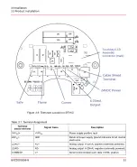
The installation of the SF910i begins with the selection of station address. SF910i can
be physically installed on the burner, and then it can be wired as needed. Installation
terminates with the correct procedure to close the cover of the enclosure to maintain the
explosion proof capability and with the preliminary operations and adjustments.
To meet EMC specifications, it is mandatory to follow the recommendations given in
.
SF910i comes from the factory already loaded with the factory-default configuration.
This configuration could be not suitable to correctly discriminate the presence of
the flame in the target burner. Therefore, for safety reasons, the SF910i will power-up
in a safe state (First-Time Power-Up state - FTPU) in which the flame relay will
never energize, even if the local display shows active signal flame algorithm vote
for flame present.
SF910i exits from this first-time power-up state only after the default setting is changed
or confirmed either on local or from remote through Flame Explorer.
While in FTPU state, the flame LED blinks red slowly.
3.3.1
Summary of Installation Procedure
The installation procedure refers to the actions required to install the SF910i up to the
point when it can be powered, and it can begin to roughly detect a flame. Now, the user
will be ready for the next phase (configuration and tuning for best performance).
Installation procedure:
–
Preliminary steps (air flow, ESD precautions, special handling, unpacking, and
inspection)
–
Protocol and station address selection
–
Physical installation
–
Wiring
–
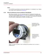
Closing the enclosure
The details of the above installation steps are discussed in the following sub-sections.
8VZZ005286 B
41
3 Installation
3.3 Product Installation
Содержание Uvisor SF910i
Страница 1: ...Combustion Instrumentation User Manual Uvisor SF910i Integrated SafeFlame Scanner PROCESS AUTOMATION...
Страница 2: ......
Страница 6: ......
Страница 20: ...8VZZ005286 B 20...
Страница 30: ...8VZZ005286 B 30...
Страница 67: ...Figure 7 5 Version Display in Normal Mode 8VZZ005286 B 67 7 Operating Display 7 5 Version Display...
Страница 68: ...8VZZ005286 B 68...
Страница 78: ...8VZZ005286 B 78...
Страница 90: ...8VZZ005286 B 90...
Страница 92: ...8VZZ005286 B 92...
Страница 97: ...Figure 14 2 Flame Temperature Parameters Screen 8VZZ005286 B 97 14 Flame Temperature Measurement...
Страница 98: ...8VZZ005286 B 98...
Страница 108: ...8VZZ005286 B 108...
Страница 114: ...8VZZ005286 B 114...
Страница 118: ...8VZZ005286 B 118...
Страница 125: ...8 Fit in place the SF910i Flame Scanner 8VZZ005286 B 125 19 Repair and Replacement 19 2 Fiber Optic Replacement...
Страница 126: ...8VZZ005286 B 126...
Страница 128: ...8VZZ005286 B 128...
Страница 130: ...8VZZ005286 B 130...
Страница 150: ...8VZZ005286 B 150...
Страница 151: ...Appendix E Drawings 8VZZ005286 B 151 E Drawings...
Страница 152: ...Figure E 1 Enclosure Quick Release Connector and Version LOS 8VZZ005286 B 152 E Drawings...
Страница 153: ...Figure E 2 Enclosure NPT Cable Inlet and Version LOS 8VZZ005286 B 153 E Drawings...
Страница 154: ...Figure E 3 Enclosure Quick Release Connector and Version FOC 8VZZ005286 B 154 E Drawings...
Страница 155: ...Figure E 4 Enclosure NPT Cable Inlet and Version FOC 8VZZ005286 B 155 E Drawings...
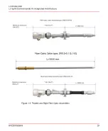
Страница 156: ...Figure E 5 FOC Flexible Assembly 8VZZ005286 B 156 E Drawings...
Страница 157: ...Figure E 6 FOC Rigid Assembly 8VZZ005286 B 157 E Drawings...
Страница 160: ...Figure E 9 Bailey Flame ON Standard Replacement 8VZZ005286 B 160 E Drawings...
Страница 161: ...Figure E 10 Typical Bailey Flame ON Installation 8VZZ005286 B 161 E Drawings...
Страница 162: ...8VZZ005286 B 162...
Страница 164: ...F 1 Earth Connection Cable Figure F 1 Earth Connections 8VZZ005286 B 164 F Cables F 1 Earth Connection Cable...
Страница 170: ...8VZZ005286 B 170...
Страница 172: ...Figure G 1 Diaphragm for SF910i FOC Scanner 8VZZ005286 B 172 G Fittings G 1 TU_KIT03 Set of Diaphragms for SF910i FOC...
Страница 178: ...G 7 Counter Flange 8VZZ005286 B 178 G Fittings G 7 Counter Flange...
Страница 179: ...Figure G 7 Boiler Mounting Counter Flange for FOC Installation 8VZZ005286 B 179 G Fittings G 7 Counter Flange...
Страница 189: ......


