


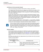


Pointing out on this subject, that the topology of a RS485 network is a “bus”. Therefore,
the network cable must be routed starting from the master station (usually a system or
a DCS interface in a control room), and passing relatively close to each SF910i ending
in a junction box located close to the last (most remote) unit. Both ends of the network
cable must be terminated with a resistor equal to the characteristic impedance of the
network. Close to each SF910i, the network must be provided with a junction box. From
that junction box, a short piece (“stub”) of network cable will reach the SF910i. The
maximum length of this “stub” is limited to a few meters and is strongly related to the
maximum transmission speed that can be used on the network and to the total number
of stubs. The shorter the stub, the higher the speed.
The above short considerations about bus network topology are enough to point out the
next important concept. The topology of the network is not always (is rarely) equal to the
topology of the remaining wiring needed to power-on and to interface the SF910i to the
Burner Management System. The most obvious topology for all cabling except the
network is a star configuration, not a bus. The center of the start is somewhere located
in the control room or in the electronics cabinet room, while the points of the star are
located in the junction box, above mentioned, close to each SF910i. From the junction
box to the SF910i, ABB suggests using a single special cable designed for the purpose.
See
for more details. The user can also use a number of standard cables
readily available on the market.
Intentionally avoided to discuss the simple case of a system made of a single SF910i.
In this case, the bus topology is coincident with the start topology. Of course, the
user can lay-out the network and the other wiring on the same cable path.
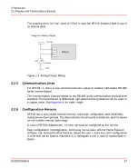
With some restriction, and with the use of copper to fiber-optic converters, the
RS-485 network can be implemented in a star topology, thus making possible to
use the same cable routing paths as the rest of the wiring.
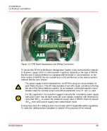
If the user connect the relay contact(s) to a circuit whose voltage is higher than
24V
DC
nominal (for instance to 220V
AC
), then this part of the wiring must be
implemented following compliance with all applicable normative.
8VZZ005286 B
40
3 Installation
3.2 Networking Preparation
Содержание Uvisor SF910i
Страница 1: ...Combustion Instrumentation User Manual Uvisor SF910i Integrated SafeFlame Scanner PROCESS AUTOMATION...
Страница 2: ......
Страница 6: ......
Страница 20: ...8VZZ005286 B 20...
Страница 30: ...8VZZ005286 B 30...
Страница 67: ...Figure 7 5 Version Display in Normal Mode 8VZZ005286 B 67 7 Operating Display 7 5 Version Display...
Страница 68: ...8VZZ005286 B 68...
Страница 78: ...8VZZ005286 B 78...
Страница 90: ...8VZZ005286 B 90...
Страница 92: ...8VZZ005286 B 92...
Страница 97: ...Figure 14 2 Flame Temperature Parameters Screen 8VZZ005286 B 97 14 Flame Temperature Measurement...
Страница 98: ...8VZZ005286 B 98...
Страница 108: ...8VZZ005286 B 108...
Страница 114: ...8VZZ005286 B 114...
Страница 118: ...8VZZ005286 B 118...
Страница 125: ...8 Fit in place the SF910i Flame Scanner 8VZZ005286 B 125 19 Repair and Replacement 19 2 Fiber Optic Replacement...
Страница 126: ...8VZZ005286 B 126...
Страница 128: ...8VZZ005286 B 128...
Страница 130: ...8VZZ005286 B 130...
Страница 150: ...8VZZ005286 B 150...
Страница 151: ...Appendix E Drawings 8VZZ005286 B 151 E Drawings...
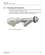
Страница 152: ...Figure E 1 Enclosure Quick Release Connector and Version LOS 8VZZ005286 B 152 E Drawings...
Страница 153: ...Figure E 2 Enclosure NPT Cable Inlet and Version LOS 8VZZ005286 B 153 E Drawings...
Страница 154: ...Figure E 3 Enclosure Quick Release Connector and Version FOC 8VZZ005286 B 154 E Drawings...
Страница 155: ...Figure E 4 Enclosure NPT Cable Inlet and Version FOC 8VZZ005286 B 155 E Drawings...
Страница 156: ...Figure E 5 FOC Flexible Assembly 8VZZ005286 B 156 E Drawings...
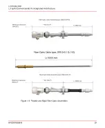
Страница 157: ...Figure E 6 FOC Rigid Assembly 8VZZ005286 B 157 E Drawings...
Страница 160: ...Figure E 9 Bailey Flame ON Standard Replacement 8VZZ005286 B 160 E Drawings...
Страница 161: ...Figure E 10 Typical Bailey Flame ON Installation 8VZZ005286 B 161 E Drawings...
Страница 162: ...8VZZ005286 B 162...
Страница 164: ...F 1 Earth Connection Cable Figure F 1 Earth Connections 8VZZ005286 B 164 F Cables F 1 Earth Connection Cable...
Страница 170: ...8VZZ005286 B 170...
Страница 172: ...Figure G 1 Diaphragm for SF910i FOC Scanner 8VZZ005286 B 172 G Fittings G 1 TU_KIT03 Set of Diaphragms for SF910i FOC...
Страница 178: ...G 7 Counter Flange 8VZZ005286 B 178 G Fittings G 7 Counter Flange...
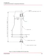
Страница 179: ...Figure G 7 Boiler Mounting Counter Flange for FOC Installation 8VZZ005286 B 179 G Fittings G 7 Counter Flange...
Страница 189: ......